
Three-way operation of the dynamic braking circuit
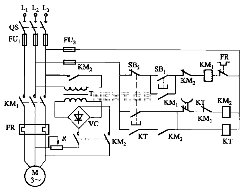
The circuit utilizes a time relay, which is a crucial component for controlling the duration of the braking process. The time relay KT is designed to introduce a specific delay before the braking action is initiated. This delay can be adjusted based on the requirements of the application, allowing for flexibility in operation.
In the circuit, the input signal activates the time relay, which then begins its timing sequence. Once the preset time elapses, the relay contacts close, triggering the braking mechanism. The relay's timing can be set using variable resistors or capacitors, depending on the design, enabling precise control over the braking duration.
The overall functionality of the circuit is essential in applications where controlled deceleration is necessary, such as in motor control systems or automated machinery. By regulating the braking time, the circuit helps prevent mechanical stress and enhances safety during operation. Proper selection of the time relay's specifications, such as its voltage rating and timing range, is vital for ensuring reliable performance in the intended application. Circuit shown in Figure 3-135. Braking time is determined by the time relay KT.
Related Circuits
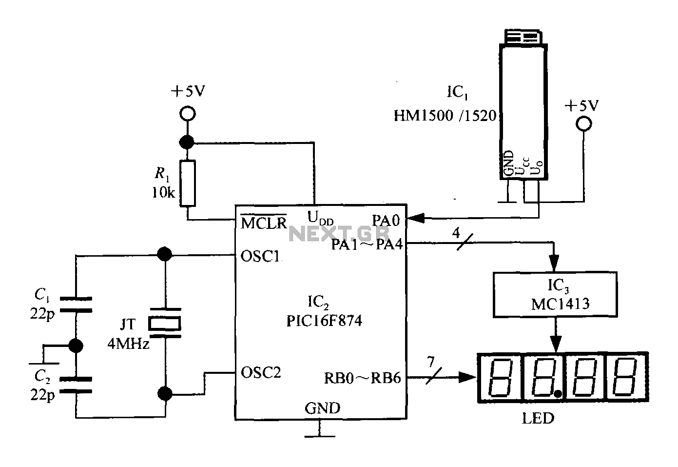
An intelligent humidity meter circuit utilizing the HM1500/1520 humidity sensor and a microcontroller configuration. The circuit operates on a +5V power supply and incorporates four common cathode LED digital displays. It employs three integrated circuits: IC1 is the HM1500/1520...
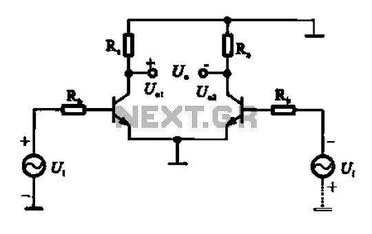
An amplifier circuit is designed to handle an assumed input consisting of two equal and opposite polarity signals, known as a differential mode signal. The two tube collector currents, Ic and IC7, are balanced in such a way that...
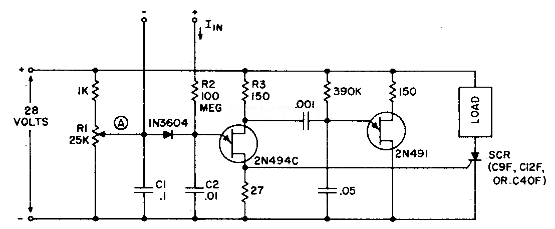
The circuit can function as a sensitive current detector or a voltage detector with high input impedance. Resistor Rl is configured so that the voltage at point (A) is V2 to a few volts below the threshold that activates...
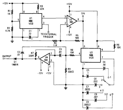
When this circuit is connected to a filter and an oscilloscope, the oscilloscope displays the filter's frequency response. A frequency that sweeps from low to high is applied to a filter. The oscilloscope is triggered by the start of...
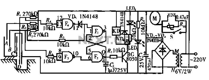
The circuit operates by monitoring the water level in a tank. When the water level falls below a specified point (F), the RS flip-flop (F2) is activated, producing a high Q output that energizes a relay to start the...
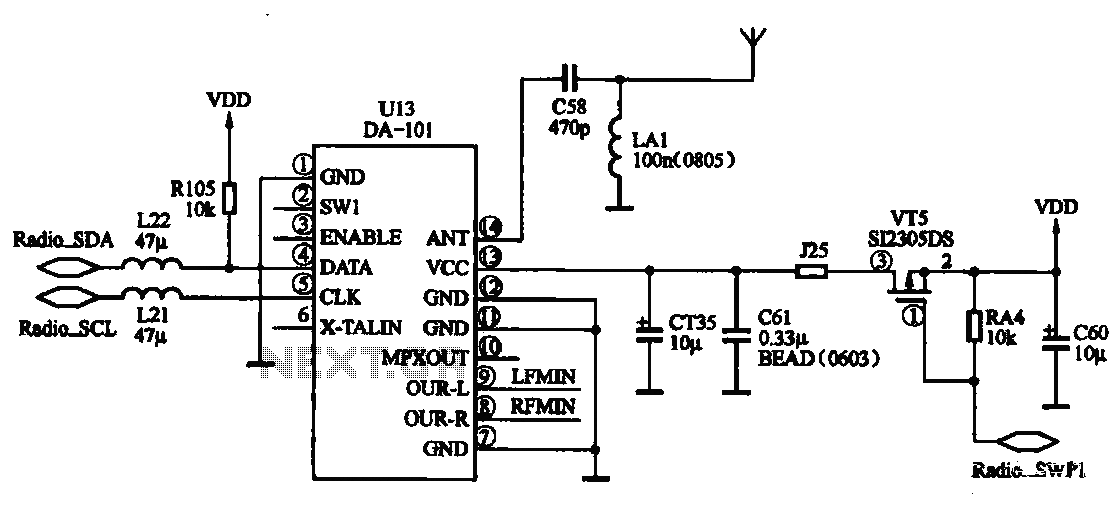
FM radio chip circuits operate differently, as illustrated by the DA-101 chip FM radio circuit. In this configuration, the FM radio broadcast program is received through the headset jack, which functions as an antenna. The signal captured by the...