
Thyristor overcurrent protection circuit 2
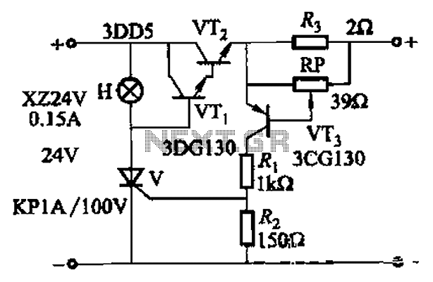
This circuit utilizes a thyristor for overcurrent protection, which is a crucial component in safeguarding electronic systems from damage due to excessive current. The thyristor operates by remaining in a conducting state until the current flowing through it falls below a certain threshold. In this configuration, transistors VTi and VT2 are employed to monitor the current level. When the current exceeds the predefined setpoint, the circuit triggers the thyristor to turn off, effectively disconnecting the load and preventing potential damage.
The inclusion of an adjustment potentiometer (RP) provides flexibility in setting the desired current threshold. This allows for customization based on the specific requirements of the application. The adjustment can be made by rotating the potentiometer, which modifies the resistance in the circuit, thus changing the voltage at the trigger input of the thyristor.
The indicator H serves as a visual alert, illuminating when an overcurrent condition has been detected. This feature is essential for operators to quickly identify issues within the system and take necessary actions to mitigate risks.
Overall, the circuit design emphasizes rapid response to overcurrent situations, ensuring that the electronic system remains protected while allowing for user-defined current settings through the adjustable potentiometer. The integration of these elements makes the circuit a reliable solution for managing current levels in various electronic applications.Adjusting Ro or RP, you can change over the current setpoint. Circuit shown in Figure 14-98. Overcurrent, V conduction thyristor, transistor VTi, VT2 off immediately cut off th e power play fast protection, the indicator H lights. Adjustment potentiometer RP, can change over the current setpoint.
Related Circuits
An FM transmitter, commonly referred to as an FM transmitter, utilizes two transistors, specifically the 2N2222 model. When in operation, this FM transmitter requires a 9-volt battery for power and operates with an antenna that is less than 12...

This DC negative-voltage generator based on the 555 produces a negative output voltage equal to approximately 2 times the DC supply voltage. The described circuit utilizes the popular 555 timer IC configured in an astable or monostable mode to generate...
This circuit automatically activates and deactivates a motorcycle's headlight, functioning independently of both the light and ignition switches, as long as the battery is fully charged. The initial stage employs a 220-ohm resistor and ZD1 to keep transistor Q1...

A simple digital circuit is presented that can be used to precisely control the AC power supply. This circuit does not include a digital-to-analog conversion component. In its application, effective control is established through a computer system that sends...
The circuit operates based on a desired temperature setting. It can be utilized for various applications, such as turning on a fan at a specified temperature or activating an emergency temperature alarm. The power supply for the circuit can...
Full short-circuit and overcurrent protection is given by this circuit suitable for workbench applications in technical schools and laboratories where there is a need to work directly with the mains. Additional features are a clearly visible red lamp indicating...