
Tilt Sensor Alarm Circuit

The tilt sensor alarm circuit utilizes a tilt sensor, which is a device that detects the orientation of an object. When the object tilts beyond a certain angle, the sensor triggers the alarm circuit. The primary components of this circuit include a tilt sensor, a transistor, a resistor, and a power supply.
The tilt sensor typically consists of a conductive ball within a sealed enclosure that connects two conductive contacts. When the sensor tilts, the ball rolls and completes the circuit, allowing current to flow. This current is directed to the base of the transistor, which acts as a switch.
When the transistor is activated, it allows current to flow from the collector to the emitter, which can be used to drive an alarm or indicator, such as a buzzer or LED. The resistor is used to limit the current flowing into the base of the transistor, ensuring it operates within safe parameters.
The power supply for the circuit can be a standard battery, ensuring portability and ease of use. The circuit can be assembled on a breadboard for prototyping or soldered onto a printed circuit board (PCB) for a more permanent solution.
This simple tilt sensor alarm circuit is ideal for applications such as security systems, where it can alert users to unauthorized movement or tampering of objects. Its low cost and ease of assembly make it accessible for hobbyists and professionals alike.Ultra simple circuit of the tilt sensor alarm presented here can be fabricated using readily available inexpensive components. The circuit is a true transi. 🔗 External reference
Related Circuits

As shown in FIG XTR108, a four-wire RTD is connected to the circuit. In practical applications, the lead resistance of a four-wire RTD is typically not equal, which necessitates the use of a precision operational amplifier, OPA277, to minimize...
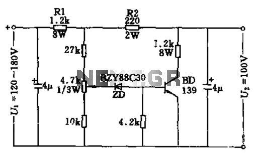
The circuit features no-load and short circuit protection mechanisms. To accommodate short circuit conditions, it is necessary to increase resistors R1 and R2 to allow for power dissipation; for example, R1 can be set to 1.2kΩ with a power...

The circuit depicted in Figure 3-193 illustrates a separately excited DC motor. The brake circuit is not activated; therefore, positive reversals occur alternately using a delay action relay, ensuring that the motor reverses direction after coming to a stop. The...
This index is organized alphabetically by each word (excluding prepositions). For instance, the "Frost Alarm" will be listed under both "A" and "F". To efficiently locate a circuit, utilize the top index or employ your browser's search feature. In...

The PWM circuit is causing the inverter's current consumption to reach a dangerous level of 14 Amps. A potential solution involves reducing the drive voltage to the gates of the MOSFETs by controlling the base voltage of the buffer...
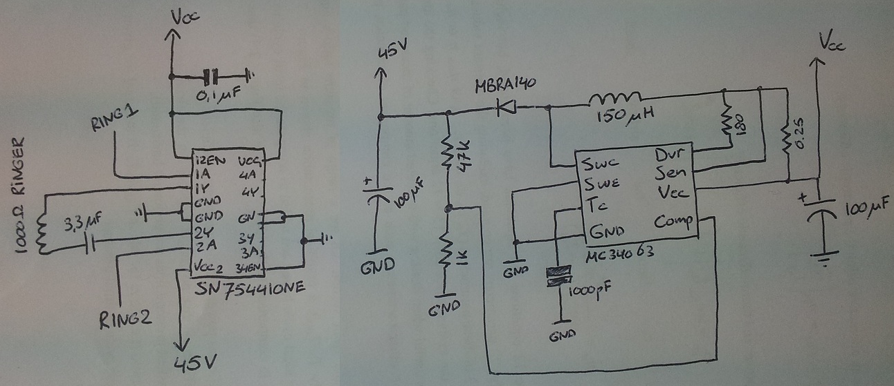
The process involves adapting an old phone for Bluetooth functionality, specifically testing the ringer circuit constructed using schematics from Sparkfun. When connecting a section of the schematic to a 3.5V source (Vcc), an output voltage of 45V is observed,...