
Timed Beepers
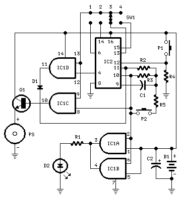
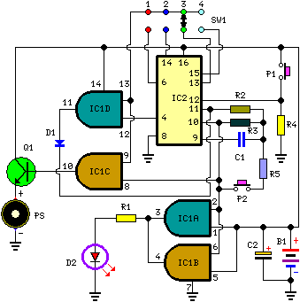
This alerting circuit utilizes an integrated circuit (IC) timer, specifically IC2, which can be a 555 timer or a similar device configured in astable mode. The timing components R3 and C1 dictate the oscillation frequency, which is critical for determining how long the alert will sound. The output from IC2 is fed into a series of logic gates (IC1A, IC1B, IC1C, and IC1D) to manage the LED and piezo sounder. The flashing LED serves as a visual cue that the circuit is operational, while the piezo sounder provides an auditory alert.
SW1 acts as a selector switch, allowing the user to choose different timing intervals by connecting specific pins of IC2 to the circuit. This flexibility is essential for various applications, such as games or timed tasks. The design also incorporates a reset mechanism via P1, which initializes the timer, and P2, which allows for an early termination of the alert.
The circuit's performance can be influenced by the resistor values used, particularly R5, which affects the timing reset speed. Adjusting this resistor must be done carefully to maintain the circuit's functionality without compromising the oscillator's operation. Overall, the circuit provides a practical solution for timing applications, combining visual and auditory signals to enhance user experience.This circuit is intended for alerting purposes after a certain time is elapsed. It is suitable for table games requiring a fixed time to answer a question, or to move a piece etc. In this view it`s a modern substitute for the old sandglass. Useful also for time control when children are brushing teeth (at least two minutes!), or in the kitchen, an d so on. Pushing P1 resets IC2 that start oscillating at a frequency fixed by R3 & C1. With values shown, this frequency is approx. 4Hz. The LED D2, driven by IC1A & B, flashing at the same oscillator frequency, signals proper circuit operation. SW1 selects the appropriate pin of IC2 thus adjusting timing duration: When the selected pin of IC2 goes high, IC1C drives Q1 and the piezo sounder beeps intermittently at the same frequency of the LED.
After approx. 7. 5 seconds pin 4 of IC2 goes high and IC1D stops the oscillator through D1. If you want to stop counting in advance, push P2. SW1 can be any type of switch with the desired number of ways. If you want a single fixed timing duration, omit the switch and connect pins 9 & 13 of IC1 to the suitable pin of IC2. The circuit`s reset is not immediate. Pushing P2 forces IC2 to oscillate very fast, but it takes some seconds to terminate the counting, especially if higher timer`s duration is chosen and the pushbutton is operated when the circuit has just started.
In order to speed the reset, try lowering the value of R5, but pay attention: too low a value can stop oscillation. 🔗 External reference
Related Circuits
Although many album titles that were once available on vinyl are gradually being released as CDs, not all are accessible. There may be valuable records in a collection that one wishes to convert to CDs. Preserving a CD is...

This circuit is designed for alerting purposes after a predetermined time has elapsed. It is ideal for tabletop games that require a fixed duration for answering questions or moving pieces. In this context, it serves as a modern alternative...
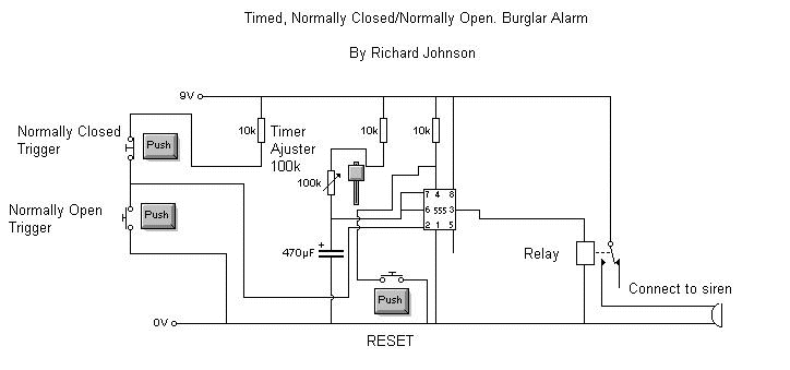
This is a simple but effective alarm circuit that can reset itself after a user-defined time. It features normally open and normally closed triggers, enhancing its practicality. The circuit utilizes a 555 timer, allowing the alarm to automatically reset...
This circuit is designed for alerting purposes after a specified duration has elapsed. It is suitable for table games that require a fixed time limit to answer a question or to move a piece, serving as a modern substitute...

This is a single-zone alarm system featuring independently adjustable Exit, Entry, and Siren Cut-Off timers. It is compatible with standard normally-closed input devices such as magnetic-reed contacts, foil tape, and passive infrared sensors (PIRs). A mains power supply can...

This circuit illustrates the use of the 4060 IC in a timed beeper electronic circuit diagram. It is suitable for table games that require a fixed time for players to respond. The 4060 IC is a versatile integrated circuit that...