
Bipolar stepper motor driver circuit diagram

This circuit design effectively leverages operational amplifiers and feedback mechanisms to control the operation of a bipolar stepper motor. The integration of two integrators (A1 and A3) with an amplifier (A2) in a series configuration allows for the generation of a stable oscillating signal, which is crucial for driving the stepper motor. The LM324 quad operational amplifier is a versatile component that can accommodate multiple functions within a single package, thus minimizing the overall footprint of the circuit.
Capacitor C1 is a critical element in the feedback loop of amplifier A2. Its role in phase correction is vital for ensuring that the motor can achieve synchronous operation, which is essential for maintaining precise control over the motor's position and speed. The ability to adjust the frequency through potentiometers R3 and R6 offers flexibility in application, enabling the circuit to cater to various operational requirements. The specified frequency range of 8 Hz to 80 Hz provides a broad spectrum of control, allowing for both slow and fast motor movements.
The incorporation of switch S1 for reversing the motor's direction adds to the versatility of the circuit, making it suitable for applications that require bidirectional movement. The use of push-pull emitter followers, utilizing power Darlington transistors V1 and V4, ensures that the output signal is sufficiently amplified to drive the stepper motor effectively. This amplification stage is crucial as it allows the circuit to handle the higher current demands of the motor without compromising performance.
In summary, this circuit design is well-structured for the control of bipolar stepper motors, providing essential features such as speed and direction adjustment, phase correction for synchronous operation, and adequate signal amplification. Each component plays a significant role in ensuring the reliable and efficient functioning of the motor within the specified operational parameters.This circuit produces the power to drive a bipolar stepper motor. The rotation speed and the rotation direction of the stepper motor can be changed. This circuit consists of two integrator circuits (A1, A3) and the amplifier (A2) connected in series. This connection provides necessary feedback to get the oscillation. The circuit is u sing the quad operational amplifier LM324. The capacitor C1 is used in the feedback network of the amplifier A2, this capacitor corrects the phase. It helps the stepper motor to start and to achieve synchronous rotation. The frequency of the generator can be adjusted with the potentiometers R3 and R6 within a range from 8 Hertz to 80 Hertz.
The rotation direction of the bipolar stepper motor can be reversed by the switch S1. Push-pull emitter followers based on the complementary transistors V1. V4 (power Darlington transistors) amplify the signal to a level suitable for the bipolar stepper motor. 🔗 External reference
Related Circuits
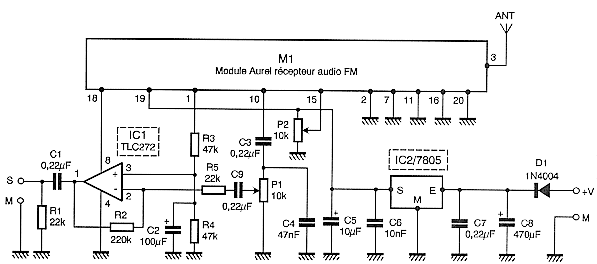
Circuit designed to alleviate concerns related to high frequency utilizes a ready-made module, specifically an Aurel audio FM transmitter. This compact circuit board, measuring 2 cm by 4 cm, supports a modulation frequency track and delivers an RF power...
This circuit is designed for precise measurement of temperature in degrees Celsius. It features a transmitter section that converts the output voltage from the temperature sensor, which is proportional to the measured temperature, into a frequency signal. This frequency...
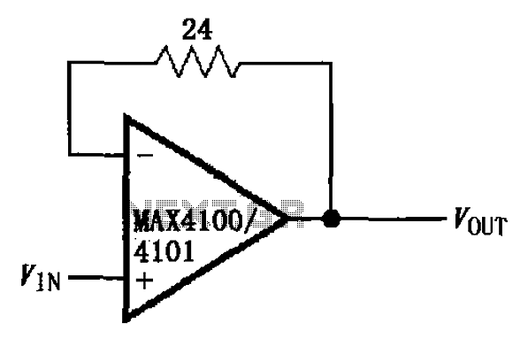
The circuit illustrated is a unit gain buffer circuit utilizing the MAX4100/4101 operational amplifiers. It incorporates a small resistor (24 ohms) within the feedback loop of the amplifier, thereby establishing a unity gain buffer. This configuration maximizes the bandwidth...
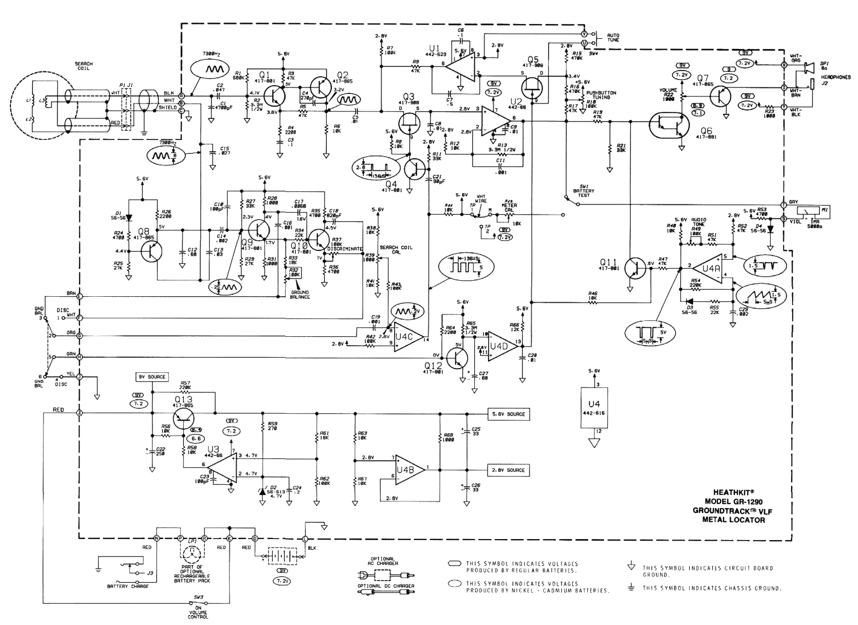
The original coil that came with the Heathkit project was preassembled at the factory. It had a diameter of around 15 cm (6 inches). A larger (30 cm, 12 inches) coil can be made using the following data. The design...
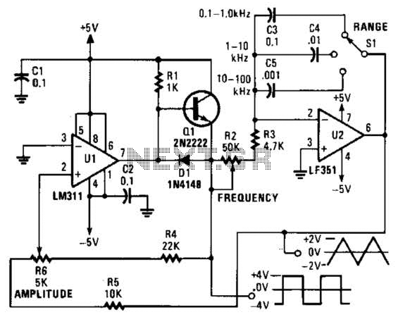
This is a simple triangle-wave generator utilizing two integrated circuit (IC) devices and a transistor. The triangle wave serves as feedback to the square-wave generator. It allows range switching across three intervals from 100 Hz to 100 kHz. Additional...
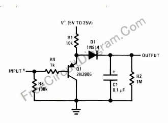
Using only a single transistor and a few passive components, a fairly sensitive peak detector circuit can be built. This peak detector circuit is suitable for various applications. The peak detector circuit utilizes a single transistor, typically configured in a...