
Timing within the one-chip computer Counter and interrupt system
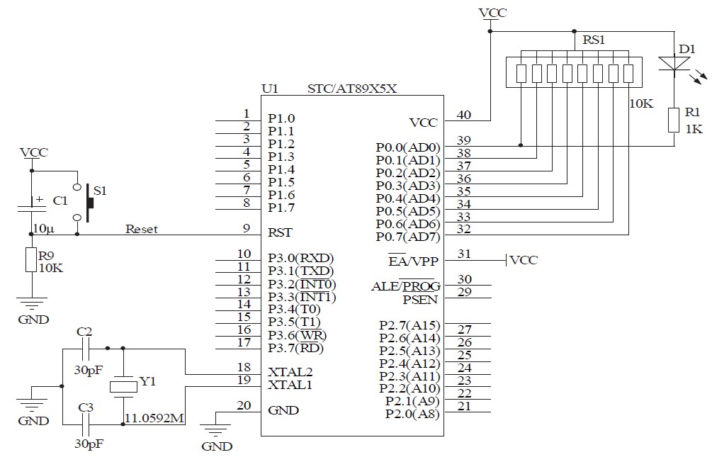
The timing/counter system in a one-chip computer is essential for various applications that require precise timing and event management. The STC89C52 microcontroller, which is commonly used in educational and experimental setups, incorporates three timers: T0, T1, and T2. Each timer can be configured to operate in different modes, such as 16-bit timer mode or 8-bit auto-reload mode, depending on the requirements of the application.
The TMOD register is critical for setting the operation mode of the timers. It allows the user to select between different modes for each timer, enabling flexibility in how the timers are utilized. For instance, in mode 0, the timer operates as a 13-bit timer, while in mode 1, it functions as a 16-bit timer. The TCON register is equally important, as it manages the control signals for starting, stopping, and monitoring the timers' status, including overflow conditions.
When the timer is started, it begins counting based on the clock pulses it receives. The internal clock of the STC89C52 is derived from the external crystal oscillator, which provides a stable frequency for accurate timing. The timer increments its count with each clock pulse, and once it reaches its maximum value, it can trigger an interrupt or reset, depending on the configuration set in the TCON register.
Using the timing/counter system effectively allows for the implementation of various time-based functions, such as generating delays, measuring time intervals, and managing periodic tasks. For example, the blinking LED experiment demonstrates how the timer can be used to create timed events, where the LED turns on and off at regular intervals based on the timer's count. This showcases the practical application of the timer in controlling external devices, enhancing the understanding of how the one-chip computer operates in real-world scenarios.This one will report about and introduce two very important resources within the one-chip computer -Timing / counter and interrupt system. Say through this, readers can know the operating principle of the timer and interrupt system of the one-chip computer.
Let us give an example of alarm clock at first, its vibrating bell after one minute regularly, this needs second hand to leave in the fake 60 times. Namely time turn number of times that second hand leave into one minute, that is number of times that count, count, come 60 then vibrating bell, and time that count each time 1 second. Timing / counter inside the one-chip computer similar with alarm clock, can set for, take timed time, regular time reach carry on corresponding operation by programming.
Count what is primary time, clock pulse that 51 one-chip computer input got after 12 frequency demultiplication by output of crystal oscillator inside one-chip computer then, so the timer can also regard as the periodic counter of the machine of the computer. Because each machine cycle includes 12 oscillating periods, so every machine cycle timer is added by 1, can regard the clock pulse input as machine periodic signal.
So the frequency is 1/12 of the Jingzhen frequency. If the Jingzhen frequency is 12MHz, then the timer receives one and inputs pulsing time each time is just 1 s. It was the Jingzhen of 11. 0592M that adopted in kit of this experiment, so it is about 1. 085 s to receive one and input pulsing time each time. Realize accurately it is very important in the actual project is employed regularly, because often need to use accurate timing for some time, then do the corresponding task at the moment reached regular time.
What regular time of realization of programming is that The simple introduction plays the one-chip computer STC89C52 on a breadboard first at first Inner timer resources. There are three timing / counter in STC89C52, it is T0, T1 and T2 respectively. Among them T0, T1 operating mode are the same, are introduced together. The operating mode of T2 has a difference slightly, does not describe here, there are real utility programs in the kit CD of the experiment.
Meanwhile, the timer sum counter in the one-chip computer multiplexes, record the external pulsing number with counter, but the timer is that one offered by one-chip computer internal clock is very stable to count the source. In originally saying, regard T0, T1 as the timer to introduce embodiment to use. After understanding one-chip computer inner timer resources, and then we come to make a detailed instruction to the register of the timer.
TMOD see Table 1, TCON see Table 3 Connect with the timer T0, timer T1 through internal bus and logical circuit, TMOD is used for setting up the operating mode of the timer, TCON is used for controlling the start of the timer, stopping, mark the overflow of the timer and cut off the situation. After setting up the operating mode of the timer and starting the timer to work, the timer works alone according to the operating mode presumed, does not take up the operating time of CPU again, may cut off CPU present operation when the counter is counted and overflow fully.
On if you can`t say by telling with the experiment of controlling an external LED to glimmer of the one piece in reader, recommend operating principle of one-chip computer and develop by procedure. This one will report about and introduce two very important resources within the one-chip computer -Timing / counter and interrupt system.
Say through this, readers can know the operating principle of the timer and interrupt system of the one-chip computer. Let us give an example of alarm clock at first, its vibrating bell after one minute regularly, this needs second hand to leave in the fake 60 times.
Turn the number of times tha 🔗 External reference
Related Circuits

An audio filter is positioned at the input of each audio integrated circuit (IC) chip to filter the audio signal intended for speakers. A low-pass filter is utilized for the woofer, while a high-pass filter is employed for midrange...
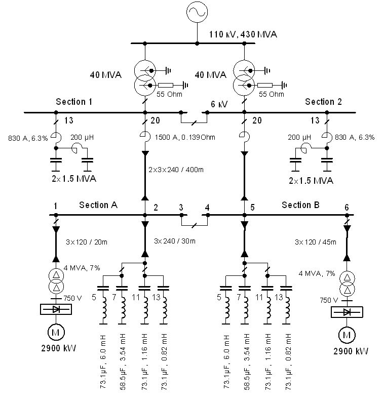
The vertical line indicates the instance of the 5th harmonic filter connection. The diagram illustrates the power system with the designed group of single-tuned filters for a system with a DC drive supplied by a 6-pulse controlled rectifier: PN...
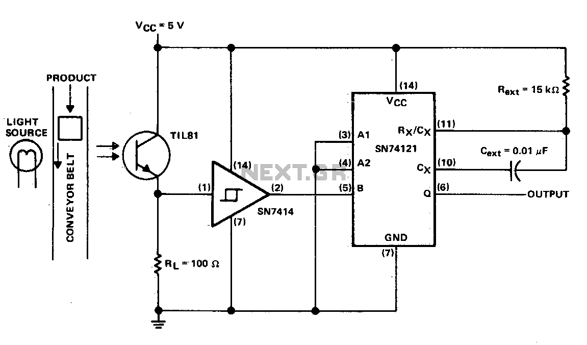
This circuit generates a pulse when an object on the conveyor belt obstructs the light source. The light source continuously keeps the phototransistor activated, resulting in a high logic level voltage at the Schmitt-trigger inverter and a TTL-compatible low...
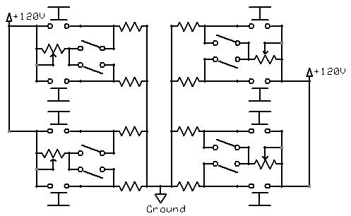
The momentary switch utilized has a safety rating of 10A. If a switch is rated for a current that is too low, the instantaneous current during the first millisecond could cause the switch contacts to fuse together. To achieve...
This technical note focuses on determining the system specifications of a CDMA receiver to establish practical specifications for a low noise amplifier and down converter. The design of a CDMA (Code Division Multiple Access) receiver necessitates a comprehensive understanding of...
This circuitry facilitates the connection between the computer's Z RS-23 serial interface and the current ring circuitry. It converts the voltage signal of the transmission into a current signal of 20 mA, achieving a maximum speed of 1200 bits....