
TIPE Project

The proposed multiplexer circuit integrates four telephone lines into a single cable infrastructure, allowing for efficient communication without the need for multiple physical lines. The design utilizes a 65C02 microprocessor, which is capable of real-time audio processing. The processor operates at a frequency of either 2 MHz or 4 MHz, ensuring that it can handle the sampling rate of 8000 samples per second required for PCM modulation.
The system's architecture incorporates Analog-to-Digital Converters (ADCs) and Digital-to-Analog Converters (DACs) to facilitate the conversion between analog audio signals and digital data. The ADC will sample the audio input, converting it into an 8-bit digital representation, while the DAC will reconstruct the audio signal for output. The implementation of A/µ law compression allows for efficient dynamic range management, which is critical in telecommunication applications to maintain audio clarity and reduce noise.
To address echo cancellation, the circuit design must consider the impedance characteristics of the telephone lines. The 600 Ohm impedance is critical for ensuring signal integrity and minimizing reflections. The use of a transformer for isolation between the telephone lines and the digital circuitry is a standard practice to protect sensitive components from high voltages present on the lines. This isolation also prevents potential damage due to mismatched impedances, which can lead to signal degradation or equipment failure.
The operational amplifiers (op-amps) in the design will serve to amplify and condition the audio signals, ensuring that they are within the appropriate voltage levels for transmission. The circuit should also include feedback mechanisms to monitor and adjust the load on the line when phones are unhooked, maintaining a stable DC voltage to keep the system operational.
In summary, the multiplexer design aims to effectively manage multiple telephone lines through a single cable while ensuring audio quality and system safety. Key considerations include impedance matching, echo cancellation, and efficient audio signal processing, all of which are essential for a reliable telecommunications system.A simple non-commercial grade multiplexer compatbile with telephones. It will supports 4 telephone lines, and will multiplex over one cable. The topic was free of choice, but had to be oriented aroudn the theme of "PrG©vision" (prediction). As you may have guessed, I chose "Multiplexing" as my topic subject. I`m hoping to learn a lot on my way, since I``m not very experienced in the field of electronics (I once tried to design a 65C02 based computer, but never got past the design stage. ), not in the field of teaching, so this page may come across as confusing in some places. I`d go with a 65C816, but I feel that for this project, something simple, and quick will do, even if I do have to pay more somewhere else for this "mistake". I`ll be modulating the voices with PCM, which means I`ll be sampling 8 bit audio at 8000 samples/second.
The 65C02 will be able to apply the A/ µ law (dynamic range compression codec ) while it`s not sampling or resending data to the multiplexer. I`m hoping to run the CPU at 2 or 4 Mhz in order to be able to sample and retransmit information in a timely fashion and to be able to apply the "compression".
I need to learn more about phone lines and impedance in order to fully understand what echo cancellation is, what wet transformers are and so forth, as this will be essential in determining how I am going to be interfacing DAC/ADCs to the phones. As anyone may know, a telephone line is composed of a long pair of copper wires (also called a twisted pair under some cases, when they are twisted around each other to avoid interference).
Depending on the length, gauge and size of these wires, they respond differently to signals: impedance. In this case, we have to take into account complex impedance modelized as (resistance, Res; and reactance, Rea): Z = Res + jRea, where j is the "imaginary" number.
In the case of telephone lines and telephones, they have been designed to operate in the 300 Hz to 3. 3 kHz band with an impedance of 600 Ohms on both ends of the line (|Z| = 600). For safety considerations (phone lines can operate at up to 130 V, non RMS), it is usually best to isolate the telephone line and the digital/analog circuitry using a 2-coil purposedly designed transformer, and to match the impedance of the line to avoid destroying equipment or to avoid echoes: this is because, if both ends of the line have unequal impedances, then the signal that is sent over the phone line will "ripple" back and forth across the phone line, or too much current will be drawn from the telephone exchange (I need a more rigrourous demonstration here.
). When "open" (all phones down), a phone line is supposed to have a very small, if not null current passing through it (in µAs), and have 48V running across the two "edges" of the line (usually -48V and ground, so that if ever the copper lines get wet, they corrode "backwards"). Ringing is supposed to occur when a 30-90V AC signal is pulsed anywhere from 20-50 Hz across the line (depends on the telephone models and countries), on top of the 48V already present.
When you unhook your phone, you create a dipole between the two edges of the line that has an impedance of about 600 Ohms, the the voltage across the line drops to about 9V as current is drawn by the telephone (this is also how the phone company knows you`re "off-hook", as in "you`ve lifted your phone") In the interests of time, since I`m only going to be hooking phones up to my multiplexer, and not hooking anything up to an actual telephone exchange, all I have to worry about it echo cancellation by balancing the load on the line when the phone is unhooked, keeping a background DC voltage to keep the phone running, and using amp-ops to receive and send voices at appropriate voltage levels over the phone lines. First the signal will be read in by the ADC and turned into an 8 bit number. The signal converted will be between -10 and 0 🔗 External reference
Related Circuits
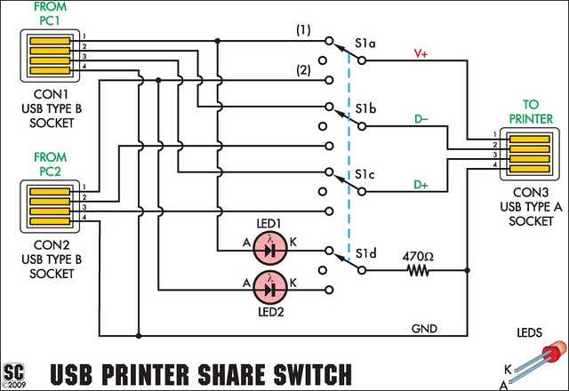
This device enables two computers to share a single USB printer or other USB devices, including external flash drives, memory card readers, or scanners. A rotary switch is used to select the PC that will access the USB device, while...
The Implantable Lamp (A3024) is a radio-controlled lamp powered by a battery. Once encapsulated in epoxy and silicone, it is waterproof and compact, allowing it to be implanted in an animal. The A3024 can theoretically be activated by any...
Over 1400 top electronics projects and electronic circuits with photos, datasheets, and easy-to-read schematics, along with explanations of how they work and how to build them. The collection comprises a vast array of electronics projects suitable for enthusiasts and professionals...
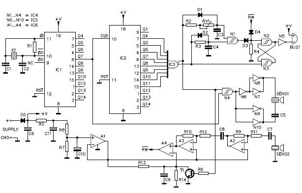
A simple ultrasonic parking sonar electronic project can be designed using this schematic circuit. This ultrasonic parking sonar project features an adjustable detection range from 5 cm to 1.5 meters and a detection angle of 5 degrees. The circuit...
The development of this interface for Echolink took some time. It utilizes the PIC16F84A microcontroller and accepts external DTMF signals from a radio. The latest version, Foxecho-k7, provides complete isolation between the radio and the PC and features automatic...
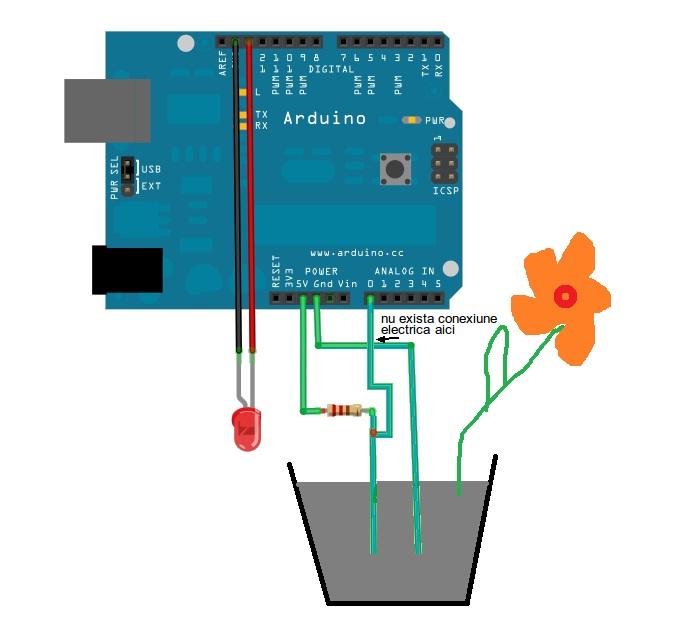
This is a simple Arduino project for a soil moisture sensor that will light up an LED at a certain moisture level. It uses the Arduino Duemilanove microcontroller. This project employs a soil moisture sensor to monitor the moisture content...