
Ultrasonic parking sonar circuit design project

The ultrasonic parking sonar circuit operates by emitting ultrasonic waves through the transmitter sensor (SENS 1: MA40A5S). These waves travel until they encounter an obstacle, at which point they are reflected back to the receiver sensor (SENS 2: MA40A5R). The time taken for the waves to return is measured, allowing the circuit to calculate the distance to the obstacle based on the speed of sound in air.
The circuit is powered by a DC power supply, which must provide a stable voltage of 10 to 15 volts to ensure reliable operation. The current consumption of 16 mA indicates a low-power design, making it suitable for automotive applications without significant impact on the vehicle's electrical system.
The adjustable detection range allows users to set the sensitivity according to their needs, with RV1 (470 kΩ) serving as the trimmer potentiometer for fine-tuning. The beep tone activated during reverse gear engagement serves as an audible alert, enhancing driver awareness of potential obstacles.
The component selection includes various resistors, capacitors, diodes, and integrated circuits that work together to process the ultrasonic signals. The CD4060, CD4020, CD4068, CD4093, CD4049, and TL074 ICs form the core logic and processing units, enabling the circuit to function effectively. The use of a transistor (T1: BC547) allows for signal amplification, ensuring that the detected signals are strong enough for processing.
Overall, this ultrasonic parking sonar circuit design offers a practical and efficient solution for enhancing vehicle safety during parking maneuvers, with a focus on simplicity and effectiveness in obstacle detection.A very simple ultrasonic parking sonar electronic project can be designed using this schematic circuit. This ultrasonic parking sonar electronic project has an adjustable detection range from 5 cm up to 1.
5 meters and a detection angle of 5 degrees. This ultrasonic parking circuit has a transmitter frequency of 45kHz and require a dc power suppl y circuit that can provide a output voltage between 10 and 15 volts at 16 mA output current (consumption current). The circuit is activated as soon as the gear is shifted in reverse (this is marked by a `bip` tone) and will detect any obstacle within the range of the sensors, the detection distance ( sensitivity) being adjusted by means of the trimmer RV1.
A distance of approx. 25 to 30cm from the backside of the car seems to be a value of practical use. Components required by this circuit are : R1 : 10M, R2 : 22K, R3, R4: 27K, R5 : 47, R6, R13 : 10K, R7, R8, R9, R10 : 15K, R11, R12 : 1K, R14:270K, D1, D2, D3, D4: 1N4148, D5 : 1N4007, C1, C2: 12pF, C3 : 22nF, C4, C7, C8: 10nF, C5, C9: 100nF, C6 : 470 µF, C10 : 10 µF, C11 : 100 µF, RV1 : 470K, IC1 : CD4060, IC2 : CD4020, IC3 : CD4068, IC4 : CD4093, IC5 : CD4049, IC6 : TL074, T1: BC547, SENS 1 :MA40A5S, SENS 2 :MA40A5R. 🔗 External reference
Related Circuits
The output frequency can be altered based on the division ratio of the comparison frequency in the 10 kHz unit, with the division ratio set to 1024 in this circuit. Given that the amateur radio bandwidth in Japan is...
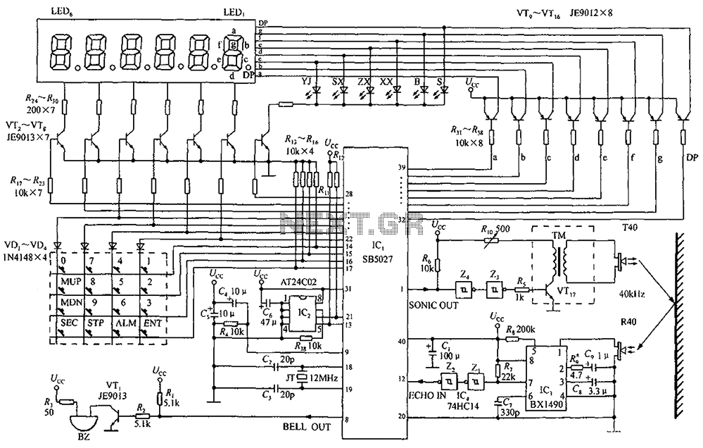
A circuit diagram of an ultrasonic range finder is constructed using a clock with a calendar and the Ultrasonic Ranging IC SB5027. The ultrasonic range finder circuit utilizes the Ultrasonic Ranging IC SB5027, which is designed to measure distances by...
This FM RF power amplifier circuit is constructed using a BLY94 transistor, which can deliver up to 50W at a frequency of 175MHz with a power gain of 7dB, resulting in approximately 5 times power amplification. However, in this...
This digital thermometer circuit diagram uses a common 1N4148 diode as the temperature sensor. The temperature coefficient of the diode is -2 mV/°C. The digital thermometer circuit leverages the characteristics of the 1N4148 diode, which has a well-defined temperature coefficient....
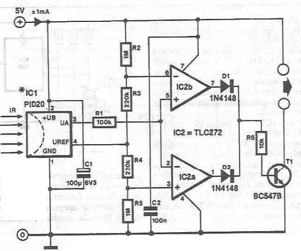
This infrared detector circuit is designed using the PID20 integrated circuit manufactured by Siemens, which converts thermal radiation into electrical impulses. It includes an operational amplifier and several electronic components. The output signal at pin 3 is compared with...
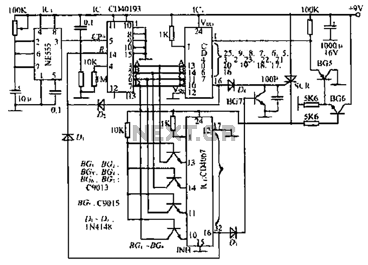
The circuit consists of an oscillator, a counter, and an Iseki circuit divided into three parts. The oscillator is based on the NE555 timer and several external RC components, generating a pulse signal for the counter. The instantaneous power...