
TL163 IC For Ultrasonic Remote Control
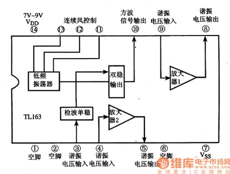
The TL163 integrated circuit serves as a pivotal component in ultrasonic remote control applications, facilitating the transmission and reception of ultrasonic signals. The circuit typically comprises several key elements: a high-gain amplifier, a detector, and a low-frequency oscillator.
The high-gain amplifier amplifies the weak ultrasonic signals received by the system, ensuring that they are sufficiently strong for further processing. This amplification is crucial for improving the signal-to-noise ratio, thereby enhancing the reliability of the remote control operation. The amplifier is often configured in a non-inverting mode to maintain signal integrity while boosting the amplitude.
The detector circuit is responsible for identifying the presence of ultrasonic signals. It converts the received sound waves into an electrical signal that can be interpreted by the control system. This conversion process is typically achieved using a piezoelectric transducer, which generates an electrical output in response to mechanical vibrations from ultrasonic waves.
Additionally, the low-frequency oscillator generates the carrier frequency used for transmitting the ultrasonic signals. This oscillator is designed to operate at frequencies typically above the audible range, ensuring that the signals remain imperceptible to human hearing while still being effective for remote control applications.
Overall, the integration of these components within the TL163 circuit allows for effective ultrasonic communication, suitable for various remote control tasks, including but not limited to, remote lighting systems, garage door openers, and other automated control systems. Proper design considerations, including component selection and layout, are essential to optimize performance and ensure reliable operation in practical applications.The following circuit shows about TL163 IC For Ultrasonic Remote Control Circuit Diagram. Features:detector, high-gain amplifier, low-frequency .. 🔗 External reference
Related Circuits
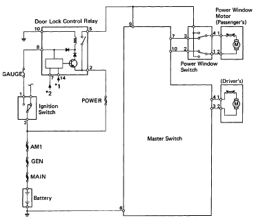
The following circuit illustrates the 1993 Toyota Hilux Pickup Power Window Control System Electrical Circuit Diagram. It is beneficial for both personal use and for mechanics during repairs. Key components include the door lock relay, junction block, power window...
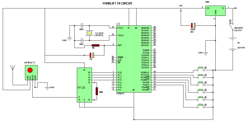
The Automatic Forklift System (AFS) is engineered to enhance the safety and efficiency of warehouse stocking processes. Traditional manually operated forklifts pose injury risks to employees. The Automatic Forklift System (AFS) aims to mitigate these hazards. The Automatic Forklift System...
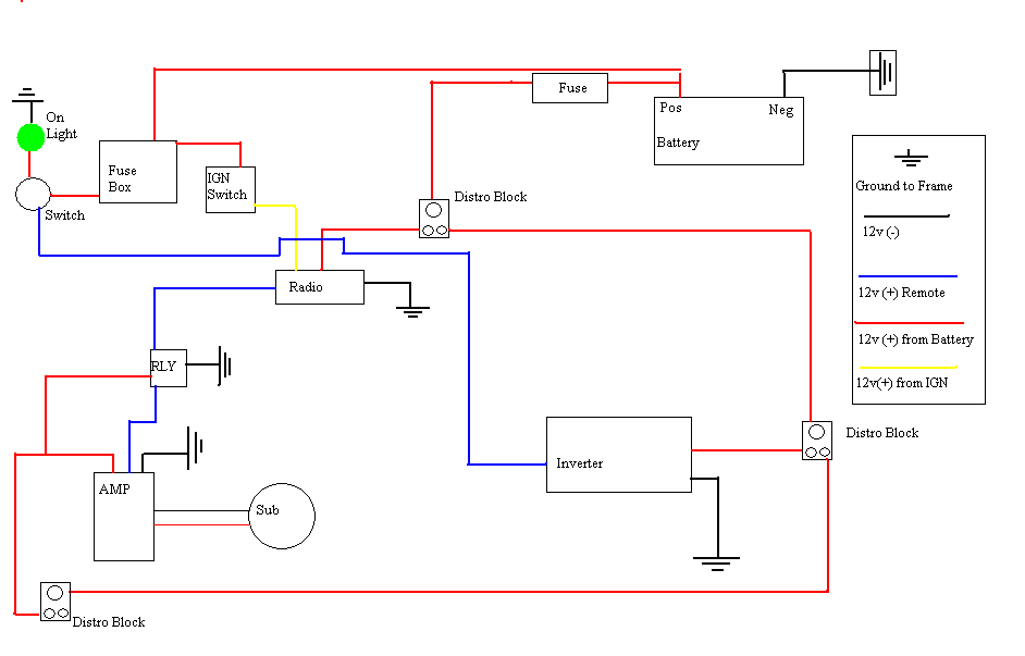
A guide for creating a remote power switch for a DC to AC inverter. The purpose is to enable the user to turn the inverter on and off remotely. The design of a remote power switch for a DC to...
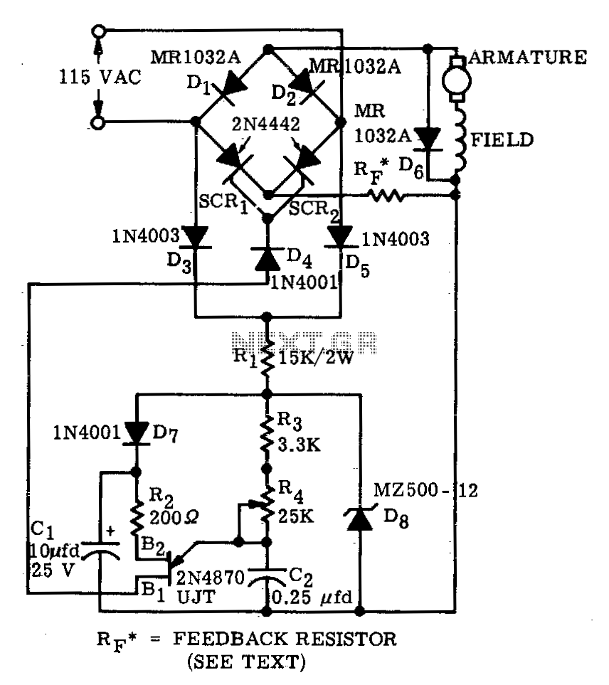
A bridge circuit consisting of two silicon-controlled rectifiers (SCRs) and two silicon rectifiers provides full-wave power to the motor. Diodes D3 and D5 deliver direct current (DC) to the trigger circuit through dropping resistors, R1. The phase delay of...
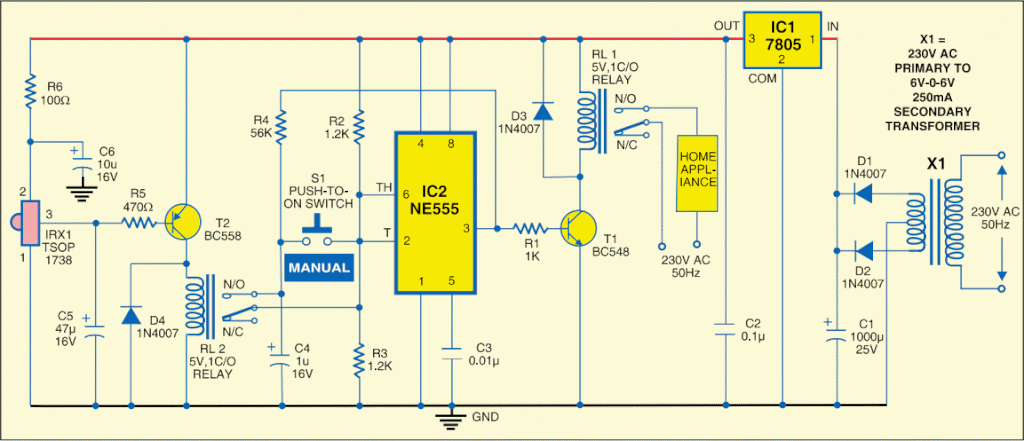
This circuit is designed to switch on or off any home or industrial appliance using a TV or DVD remote controller. The circuit can be operated up to a distance. The circuit utilizes an infrared (IR) receiver module, which detects...
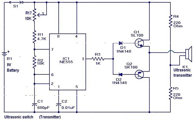
A new type of remote control operates based on ultrasonic sound. The transmitter section of the circuit is constructed around IC1 (NE 555), configured as an astable multivibrator functioning at 40 kHz. The output from IC1 is amplified by...
Warning: include(partials/cookie-banner.php): Failed to open stream: Permission denied in /var/www/html/nextgr/view-circuit.php on line 713
Warning: include(): Failed opening 'partials/cookie-banner.php' for inclusion (include_path='.:/usr/share/php') in /var/www/html/nextgr/view-circuit.php on line 713