
Ultrasonic switch
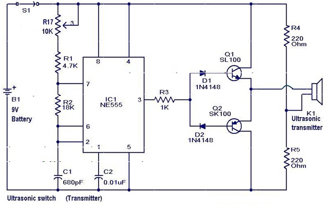
The described circuit represents an innovative approach to remote control technology, leveraging ultrasonic sound waves for signal transmission and reception. The transmitter section, centered around the NE 555 timer IC, is designed to generate a continuous 40 kHz ultrasonic signal. This frequency is chosen to ensure minimal interference from other electronic devices and to maximize the range of the remote control. The complementary transistor pair (Q1 and Q2) serves to amplify the output from the NE 555, ensuring that the ultrasonic signal is strong enough for effective transmission through the ultrasonic transmitter (K1).
The receiver mechanism is equally sophisticated. The ultrasonic sensor transducer (K2) is sensitive to the 40 kHz frequency, allowing it to detect incoming signals effectively. Once the ultrasonic signal impinges on the sensor, it generates a small voltage that is not sufficient for direct processing. Hence, this signal is routed through a two-stage amplifier consisting of transistors (Q3 and Q4), which boosts the signal strength for further processing.
Following amplification, the signal is rectified by diodes (D3 and D4), converting the AC signal into a DC voltage that can be utilized by subsequent circuitry. The rectified output is then fed into an operational amplifier configured as a comparator. This configuration is critical, as it allows the detection of the presence of the ultrasonic signal by comparing the amplified signal against a reference voltage. When the ultrasonic signal exceeds the reference level, the comparator's output transitions, triggering the activation of transistors (Q5 and Q6).
These transistors serve as a switch to control a relay, which can manage larger loads, effectively allowing the remote control system to operate various devices or systems. The use of a relay provides electrical isolation between the control circuit and the load, enhancing safety and reliability. Overall, the circuit showcases an efficient method of remote operation using ultrasonic technology, combining signal generation, amplification, and switching in a well-integrated system.A new type of remote control based on ultra sonic sound. The transmitter part of the circuit is build around IC1(NE 555). The IC1 is wired as an astable multi vibrator operating at 40KHz. The output of IC1 is amplifier the complementary pair of transistors ( Q1 & Q2) and transmitted by the ultrasonic transmitter K1. The push button switch S1 is used the activate the transmitter. The receiver uses an ultrasonic sensor transducer (K2) to sense the ultrasonic signals. When an ultrasonic signal is falling on the sensor, it produces a proportional voltage signal at its output. This weak signal is amplified by the two stage amplifier circuit comprising of transistors Q3 and Q4.
The output of the amplifier is rectified by the diodes D3 & D4. The rectified signal is given to the inverting input of the opamp which is wired as a comparator. Whenever there is an ultrasonic signal falling on the receiver, the output of the comparator activates the transistors Q5 & Q6 to drive the relay. In this way the load connected via the relay can be switched. 🔗 External reference
Related Circuits
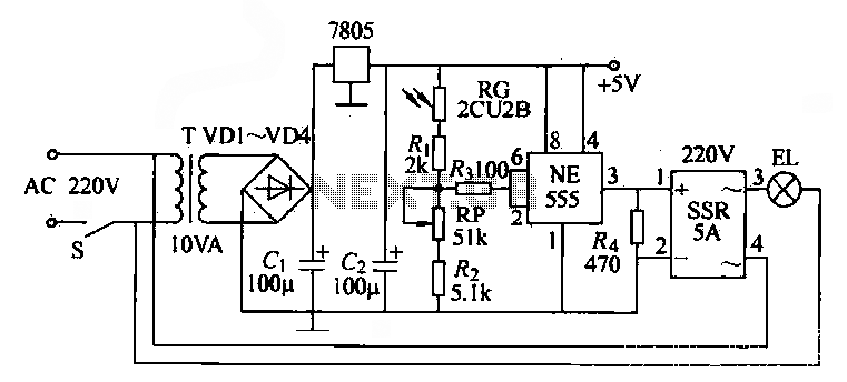
The NE555 time base circuit with an AC solid-state relay (SSR) can function as an automatic light switch circuit. The circuit diagram illustrates that during the day, the incandescent light is turned off due to the influence of the...
The ultrasonic drilling machine is essential machinery in the dairy industry for processing jewelry, primarily for natural stones, crystal agate, jade, and glass products. This machine is particularly effective for high-hardness materials, enabling both drilling and engraving. The following...
This light sensor switch circuit enables the automatic activation of a lamp when ambient light levels are low, such as during nighttime. The circuit keeps the lamp illuminated for a predetermined duration. When transistors T4 and T5 are activated,...
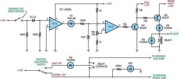
The current vehicle, a Pajero, has been modified for dual fuel operation, utilizing both petrol and gas. It is essential to operate the vehicle on petrol at regular intervals to prevent clogging of the injectors. This circuit facilitates starting...
This example presents a switch DC regulated power supply circuit designed for buck-mode +5V applications. It consists of a power supply circuit, an impulsator, a voltage sampling or pulse width modulation circuit, and a buffering driver circuit, as illustrated...
This is a simplified version of the Universal Keypad-Operated Switch. The design has been modified to reduce circuit complexity and the number of components required. As a result, the code is somewhat less secure; however, it remains adequate for...
Warning: include(partials/cookie-banner.php): Failed to open stream: Permission denied in /var/www/html/nextgr/view-circuit.php on line 713
Warning: include(): Failed opening 'partials/cookie-banner.php' for inclusion (include_path='.:/usr/share/php') in /var/www/html/nextgr/view-circuit.php on line 713