
High-torque motor speed control
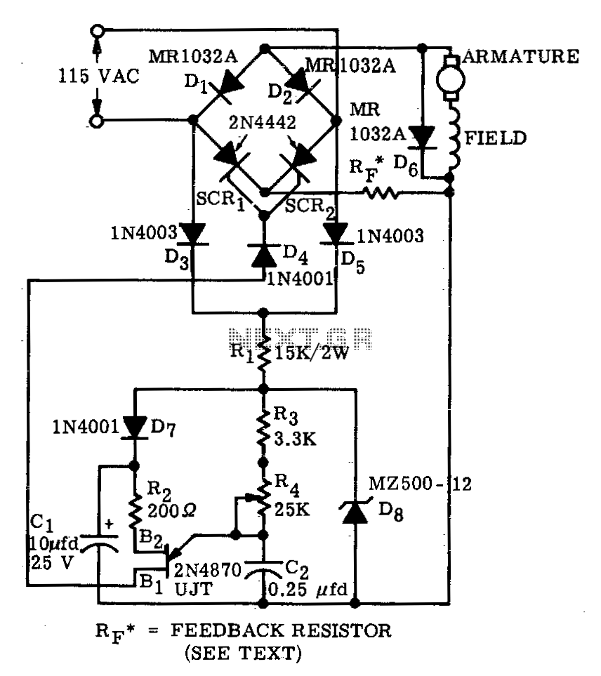
The described circuit operates as a full-wave rectifier using a bridge configuration that is particularly effective in providing controlled power to a motor. The two SCRs function as electronic switches that can be triggered to allow current to flow through the motor in both directions, thereby enabling efficient operation.
The diodes D3 and D5 play a critical role in supplying a steady DC voltage to the trigger circuit. By utilizing dropping resistors R1, the circuit ensures that the voltage level supplied to the trigger circuit is appropriate for the operation of the UJT. This setup is essential for achieving reliable SCR firing.
The charging mechanism of capacitor C2 is crucial for controlling the timing of the SCR firing. Resistors R3 and R4 form a voltage divider that, in conjunction with zener diode D8, establishes a stable reference voltage. This reference voltage is pivotal in determining the charging rate of C2, which directly influences the phase delay of SCR firing. When the voltage across C2 reaches the threshold necessary to trigger the UJT, the UJT conducts, resulting in the firing of the corresponding SCR.
Once the SCR is triggered, current flows through the motor, and the system operates until C2 discharges below the necessary threshold. The feedback resistor Rf is integral in fine-tuning the performance of the circuit. Its value must be calculated based on the specific motor characteristics and the required feedback to maintain stable operation. A well-optimized Rf value ensures that the system can adapt to varying load conditions while maintaining efficient performance.
Overall, this bridge circuit configuration is an effective solution for controlling motor power, leveraging SCR technology and feedback mechanisms to achieve precise control over motor operation.A bridge circuit consisting of two SCRs and two silicon rectifiers furnishes full-wave power to the motor. Diodes, D3 and D5, supply dc to the trigger circuit through dropping resistors, Rl. Phase delay of SCR firing is obtained by charging C2 through resistors R3 and R4 from the voltage level established by the zener diode, D8.
When C2 charges to the firing voltage of the unijunction transistor, the UJT fires, triggering the SCR that has a positive voltage on its anode When C2 discharges sufficiently, the unijunction transistor drops out of conduction. The value of Rf is dependent upon the size of the motor and on the amount of feedback desired. A typical value for Rf can be calculated 2. 🔗 External reference
Related Circuits
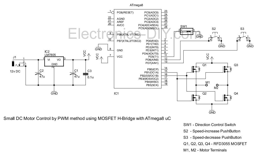
This project involves controlling a small DC motor, sourced from an old personal cassette player, using the ATmega8 microcontroller. The ATmega8 features three PWM channels, of which two are utilized in this application. The PWM signals are sent to...
The use of power MOSFETs facilitates a direct interface between logic and motor power, enabling circuit simplicity and high efficiency. This speed control circuit can be implemented on a 22-pin, double-sided, 3.5 x 4-inch printed circuit board (PCB). A...
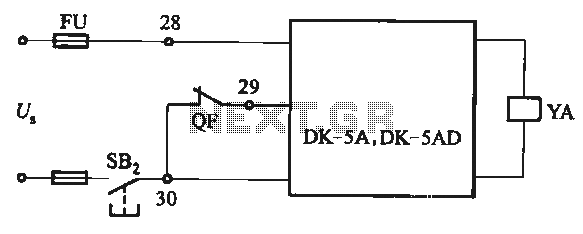
The DK-5A and DK-5AD AC power control circuit is illustrated in Figure 6-77. The figure includes a closing button (SBz) and a line (YA) connected to the closing electromagnet coil (U). This circuit is designed for the operation of...
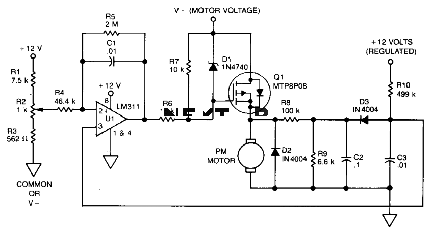
After being careful about every orientation of every transistor, a circuit board was designed around the LM387N, which was not the intended chip nor the one originally ordered (LM258, commonly referred to as LM358). During testing before adding larger...

This device functions as a convenient tool for testing infrared (IR) remote control transmitters used with televisions, VCRs, and similar devices. The IR signals emitted from a remote control are detected by the IR sensor module within the tester,...
This circuit diagram represents a remote control system utilizing DTMF (Dual Tone Multi-Frequency) signals. DTMF signals, generated by pressing numbers on a telephone keypad, serve as the control mechanism for the system. The DTMF tones are employed to modulate...
Warning: include(partials/cookie-banner.php): Failed to open stream: Permission denied in /var/www/html/nextgr/view-circuit.php on line 713
Warning: include(): Failed opening 'partials/cookie-banner.php' for inclusion (include_path='.:/usr/share/php') in /var/www/html/nextgr/view-circuit.php on line 713