Tlash exposure meter

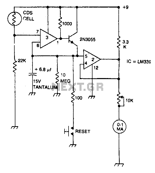
A strobe light meter captures the peak flash intensity and retains it long enough to provide a reading. The reset button must be pressed prior to each measurement.
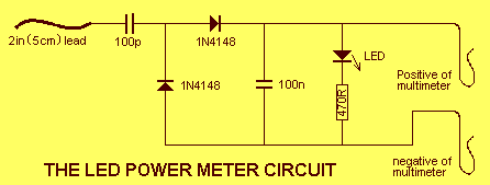
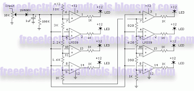
The strobe light meter operates by detecting the peak intensity of light emitted from a strobe source. It utilizes a photodetector, typically a photodiode or phototransistor, to sense the incoming light. Upon detecting a flash, the device records the maximum intensity level for a brief period, allowing the user to read the value on a digital display or analog gauge.
The circuit design includes a reset mechanism that ensures accurate measurements. The reset button is connected to a microcontroller or a timing circuit that clears any previous readings, allowing the meter to start fresh for each new measurement. When the button is pressed, it activates a discharge path for any stored charge in the sensing circuitry, ensuring that only the latest flash intensity is recorded.
Additionally, the strobe light meter may incorporate features such as a hold function, which maintains the displayed reading until the user decides to take another measurement. This is particularly useful in environments with varying light conditions or when multiple flashes are present in quick succession.
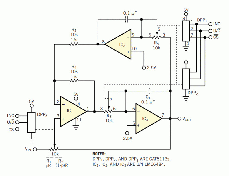
Power supply considerations are also crucial; the device typically operates on batteries or a low-voltage power source, ensuring portability and ease of use. Calibration circuits may be included to adjust for sensitivity and accuracy, allowing the meter to be fine-tuned for different strobe light conditions.
In summary, the strobe light meter is a sophisticated instrument designed to provide reliable peak intensity measurements of flash lighting, with user-friendly features such as a reset button and hold function for enhanced usability.Strobe light meter catches the peak of flash intensity and holds it long enough to give a reading The reset button must be pressed before each measurement.


