
12 Volt Lead Acid Battery Meter Led
The circuit employs the LM339 quad voltage comparator, which consists of four independent, high-speed voltage comparators. The comparators are configured to compare the voltage levels from the battery and a reference voltage. The reference voltage is established at 5 volts, serving as a threshold for the comparators. The voltage divider, composed of resistors, divides the battery voltage into smaller voltages that are fed into the negative inputs of the comparators.
When the battery voltage exceeds the reference voltage at the negative input, the output of the comparator goes low, turning on the corresponding LED. This configuration allows for a visual representation of the battery's charge status, with each LED indicating a specific range of battery voltage. The calibration process involves adjusting a potentiometer to ensure that the system accurately reflects the battery's state of charge.
The use of a 2K potentiometer provides a means to fine-tune the threshold levels at which the LEDs activate. This is crucial for ensuring that the bar graph meter accurately reflects the battery's voltage levels. The circuit can be further enhanced by incorporating temperature compensation, which would adjust the reference voltage based on the ambient temperature, thereby improving accuracy across different operating conditions.
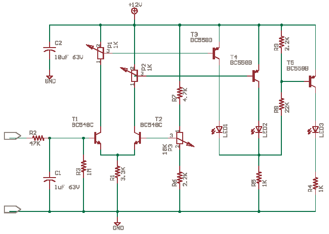
In practical applications, this circuit can be used in various battery-powered devices to monitor battery health, providing users with a simple and effective means to assess battery status. The design is flexible enough to accommodate different types of lead-acid batteries, ensuring broad applicability. Additional considerations may include implementing protection circuits to prevent over-discharge of the battery, which could extend the battery's lifespan and maintain its performance.In the circuit below, a quad voltage comparator (LM339) is used as a simple bar graph meter to indicate the charge condition of a 12 volt, lead acid battery. A 5 volt reference voltage is connected to each of the (+) inputs of the four comparators and the (-) inputs are connected to successive points along a voltage divider.
The LEDs will illumina te when the voltage at the negative (-) input exceeds the reference voltage. Calibration can be done by adjusting the 2K potentiometer so that all four LEDs illuminate when the battery voltage is 12. 7 volts, indicating full charge with no load on the battery. At 11. 7 volts, the LEDs should be off indicating a dead battery. Each LED represents an approximate 25% change in charge condition or 300 millivolts, so that 3 LEDs indicate 75%, 2 LEDs indicate 50%, etc.
The actual voltages will depend on temperature conditions and battery type, wet cell, gel cell etc. Additional information on battery maintenance can be found at: 🔗 External reference
Related Circuits
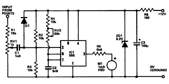
The following circuit illustrates a Tachometer Circuit Project. This circuit is constructed using the 555 Timer IC. Features include a monostable IC and voltage capabilities. The Tachometer Circuit utilizes a 555 Timer configured in monostable mode to measure the rotational...

It may be easy to find a precision voltage reference for your application; however, a programmable precision reference is another matter. The circuit in Figure 1 yields a precision reference with an LSB of 62.5 µV. The circuit is...
The circuit possesses significant educational value. It has not been tested. Users can simulate and test it or construct it to evaluate its performance. The circuit functions as a simple analog-to-digital converter. Optocouplers can be used in place of...
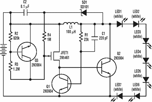
A low power, long-life LED flashlight circuit. Electronic Design proposed a simple circuit to resolve this in a recent article. The front end of their circuit draws less than a milliamp of extra current. The described LED flashlight circuit is...
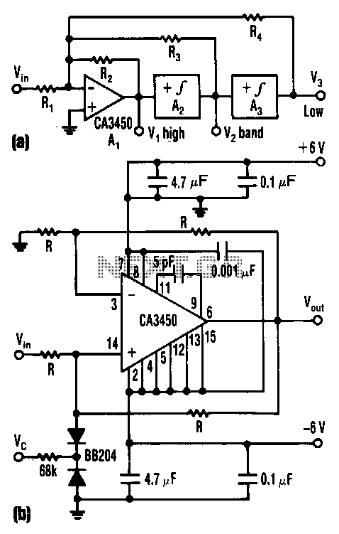
The control voltage Vc effectively adjusts the cutoff frequency w0 of this state-variable filter to any desired value, ranging from approximately 1.7 MHz to 5 MHz, using a BB 204 varicap and a resistance of 100 kΩ. Vc can...
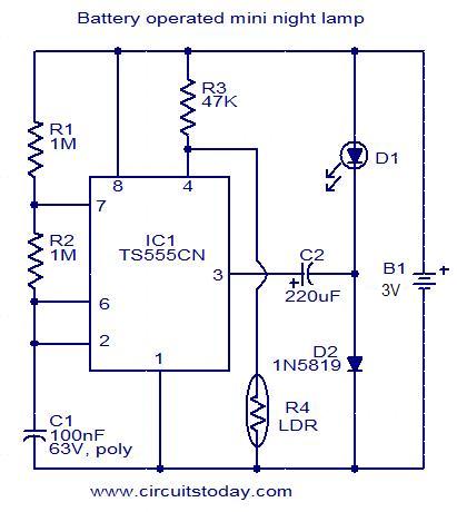
This circuit is designed as a low-power LED night lamp that automatically switches off during daytime. The CMOS timer IC TS555CN is configured as a square wave generator operating at approximately 5 Hz. The output voltage from the IC...