
High Impedance DC Voltmeter Circuit Using Op Amp

The high impedance DC voltmeter circuit is designed for accurate voltage measurements across a wide range of input voltages while minimizing loading effects on the circuit under test. The uA741 op-amp is selected for its favorable characteristics, including low input bias current and high input impedance, which is essential for high impedance applications. The non-inverting configuration allows for a straightforward voltage gain setup, where the gain can be adjusted by selecting appropriate values for resistors R1 and R2, thus enabling the user to switch between different voltage measurement ranges efficiently.
The feedback mechanism through R6 ensures that the meter's full-scale deflection occurs at a specific input voltage, enhancing the precision of the measurement. The specified 0.1 volts drop across R6 allows for a clear and consistent reference point for calibration. The inclusion of protective diodes (D1, D2, D3, and D4) is critical for enhancing the robustness of the circuit. These diodes prevent damage from overvoltage conditions, ensuring that both the IC and the measuring meter remain operational under adverse conditions.
The dual power supply configuration (+9V/-9V) is advantageous as it provides the necessary headroom for the op-amp to function effectively, allowing it to handle both positive and negative input voltages without distortion. This further ensures that the voltmeter can accurately measure AC signals when appropriately configured, making it versatile for various electronic testing applications. Overall, this high impedance DC voltmeter design is efficient, reliable, and suitable for laboratory and field use, capable of delivering precise voltage readings across a wide range of applications.This is a design for a high impedance DC voltmeter. This circuit is design with built by uA741 IC. This IC is a op-amp non-inverting DC amplifier. The IC have negative feedback that is through a DC meter requiring 1mA for full scale deflection. This is the figure of the circuit. The principle work of this circuit is since R6 is 100 Ohms, the meter will show full scale reading when the DC input voltage to pin3 is equal to the voltage drop across R6, viz 0. 1 volts. Choice of R1 and R2 for getting different voltage ranges are shown in the table. The diodes D1 and D2 protect the IC from accidental excessive input voltages and diodes D3 and D4 protect the meter from overloads.
The circuit can be powered from a +9V/-9V dual power supply. 🔗 External reference
Related Circuits
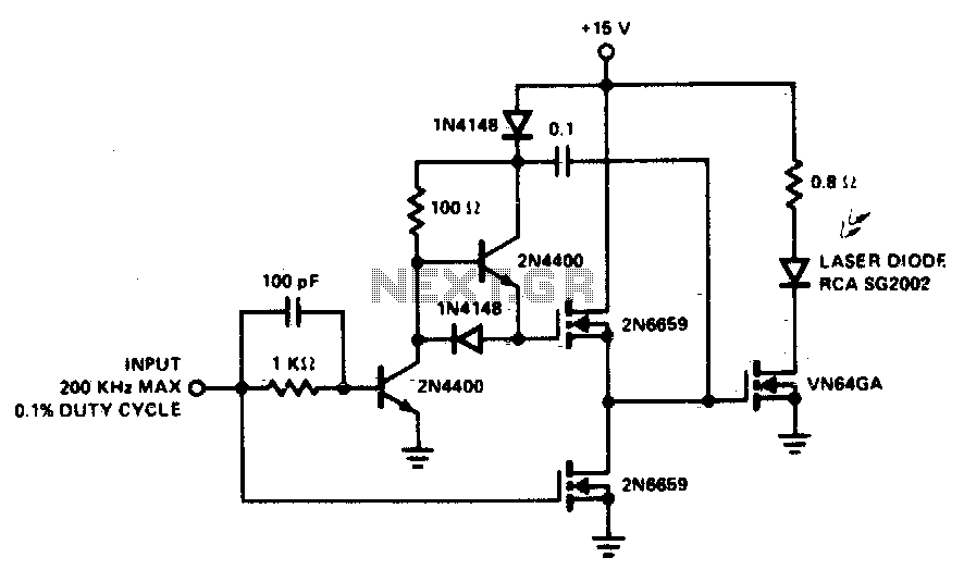
A faster driver can supply higher peak gate current to switch the VN64GA very quickly. The circuit uses a VMOS totem pole stage to drive the high power switch. The described circuit employs a high-speed driver to enhance the switching...
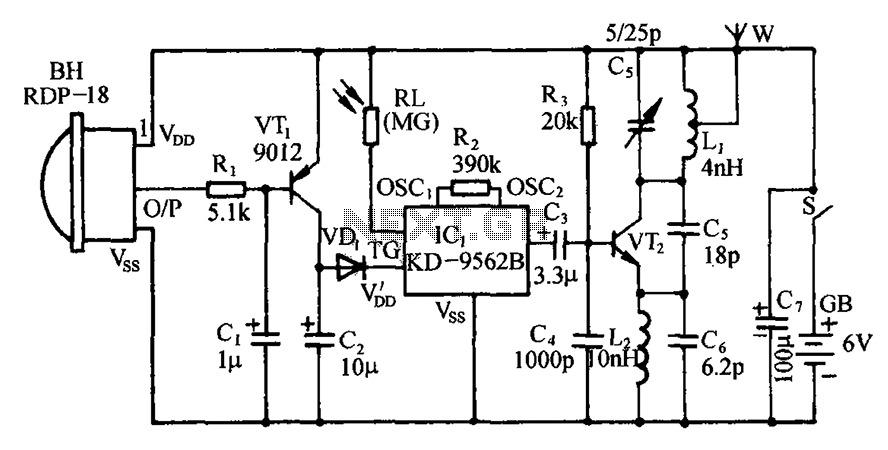
The circuit includes an infrared sensor head, electronic switches, an audible audio circuit, and an FM radio circuit. It is designed for installation in banks, treasuries, and other areas requiring supervision during evening hours in lieu of staff presence....
The circuit is placed parallel with the exit of power amplifier and gives the level of signal from output. Changing resistance R1 in the input circuit, we adapt the indication of power in the resistance of loudspeaker that we...
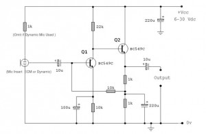
Both transistors should be low-noise types. The original circuit uses the BC650C, which is an ultra-low noise device. These transistors are now hard to find, but the BC549C or BC109C are good replacements. The circuit is self-stabilizing and will...
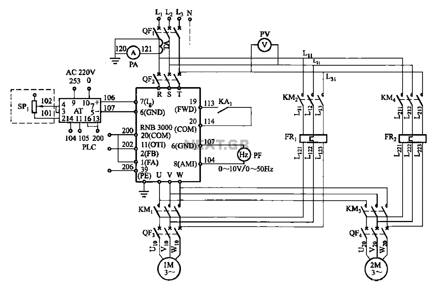
A control circuit for two motors, specifically for frequency control in a constant pressure water supply system, is illustrated in Figure 5-23. The circuit includes fault output terminals labeled 1 and 2, analog feedback current input terminals labeled 6...
When the unit is positioned near a live conductor, whether insulated or buried in plaster, capacitive coupling occurs between the live conductor and the probe. This interaction activates the counter, resulting in the LED flashing five times per second,...
Warning: include(partials/cookie-banner.php): Failed to open stream: Permission denied in /var/www/html/nextgr/view-circuit.php on line 713
Warning: include(): Failed opening 'partials/cookie-banner.php' for inclusion (include_path='.:/usr/share/php') in /var/www/html/nextgr/view-circuit.php on line 713