
TMP01 Celsius Scale Temperature Sensor
The TMP01 is a precision temperature sensor that outputs a voltage proportional to temperature. It operates on the principle of measuring the voltage across a temperature-sensitive resistor, which varies with temperature changes. The TMP01 provides a linear output voltage that can be easily interpreted by an analog-to-digital converter (ADC) or used directly in voltage-based applications.
In the schematic, the TMP01 is typically powered by a stable DC supply, often within the range of 2.7V to 5.5V. The output of the TMP01 is a voltage that corresponds linearly to the temperature in degrees Celsius, with a scale factor of 20 mV/°C. This means that at 0°C, the output voltage is 0V, and it increases by 20 mV for each degree Celsius increase in temperature.
The circuit may include additional components such as resistors for biasing, capacitors for filtering noise, and possibly an operational amplifier to enhance the output signal if needed. The output voltage can be connected to a microcontroller or a display device for real-time temperature monitoring.
In applications where precise temperature measurement is critical, the TMP01 can be integrated into systems for HVAC control, environmental monitoring, or industrial process control, ensuring accurate temperature readings for effective system management. The design should account for proper layout techniques to minimize noise and ensure signal integrity, particularly when interfacing with sensitive analog components.The schematic diagram described here is a TMP01 Celsius Scale Temperature Sensor circuit. This circuit is used to convert the VPTAT output voltage that is.. 🔗 External reference
Related Circuits

The sensitivity of the circuit can be adjusted using potentiometer P1 to avoid responding to ambient noise levels. Diodes D1 and D2 rectify the signal, while capacitor C4 provides smoothing. When the voltage across C4 exceeds 0.5 V, transistor...
This DIY magnetic field sensor circuit is straightforward and capable of detecting both static magnetic fields and those that vary at audio frequencies. The unit is designed to be user-friendly and efficient. The magnetic field sensor circuit typically employs a...
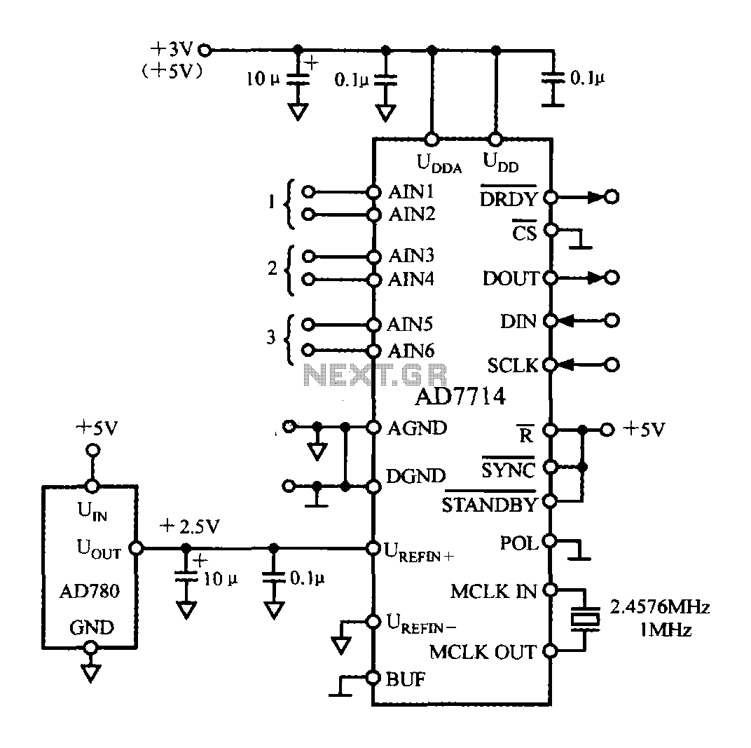
The typical application circuit for the AD7714 is illustrated in the accompanying figure. The UDD and UDDA terminals of the AD7714 can be connected to either a +3V or +5V power supply. The analog inputs are arranged as three...
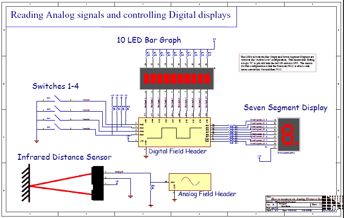
This video demonstrates the process of reading an analog voltage, computing data, and controlling LEDs using a Sharp GP2D12 Infrared (IR) sensor. The PDQ board connects to a host PC via a serial cable, operating at a baud rate...
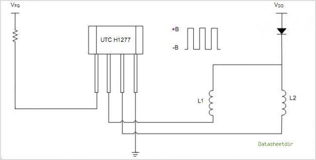
The UTC H654 is an integrated Hall sensor with complementary output drivers designed for the electronic commutation of brushless DC fans. It consists of an on-chip Hall voltage generator, a differential amplifier Schmitt trigger, and an open-collector output all...
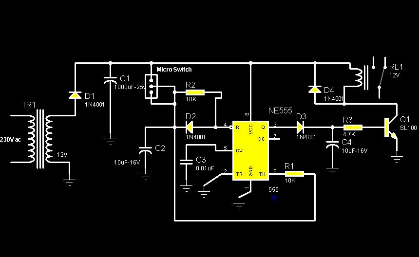
The circuit diagram illustrates a rotation sensor that activates a device, such as a motor or buzzer, when the circuit assembly is rotated. The design is based on the fundamental operation of a 555 timer. The rotation sensor circuit utilizes...