
Toggle Switch No.1 - Cmos 4013
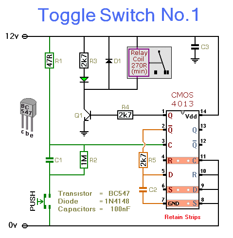
This circuit functions as a simple toggle switch, utilizing a momentary action push-to-make switch to control the state of a relay. The relay serves as an electromechanical switch, enabling the control of higher voltage or current loads while maintaining low-voltage control circuitry. The inclusion of the CMOS 4013, a dual D-type flip-flop, allows for the toggle functionality, where one half of the IC is configured to change state with each button press.
The circuit design requires careful selection of the relay based on the voltage and current specifications of the load to be controlled. The relay's coil must match the supply voltage, which can vary from 5 to 15 volts, providing flexibility for different applications. The visual indication provided by the LED enhances usability by allowing the user to easily determine the relay's status.
In terms of safety, the warning against using the on-board relay for mains voltage switching is crucial. The proximity of low-voltage components to relay contacts poses a risk of electrical shock or damage. For applications involving mains voltage, it is recommended to utilize a relay that is rated for such use and to install it in a manner that ensures adequate isolation from the control circuitry. This could involve using a separate enclosure or mounting the relay on a different board entirely.
Overall, this circuit is ideal for applications requiring a simple toggle switch mechanism, offering versatility and ease of use while emphasizing the importance of safety in higher voltage applications.This simple circuit will energize and de-energize a relay at the push of a button. Any type of momentary action push-to-make switch can be used. Pushing the button once - will energize the relay. And pushing it a second time - will de-energize the relay. I`ve drawn the circuit with a single pole relay. But you can use a multi-pole relay if it suit s your application. Only one half of the Cmos 4013 is used. So you could construct two independent toggle switches with a single IC. The circuit will work at anything from 5 to 15-volts. All you need do is select a relay with a coil voltage that suits your supply. The LED provides a visual indication that the relay is energized. In effect - it tells you whether the switch is on or off. It`s not necessary to the operation of the circuit. If you wish you may leave out R3 and the LED. Do not use the "on-board" relay to switch mains voltage. The board`s layout does not offer sufficient isolation between the relay contacts and the low-voltage components. If you want to switch mains voltage - mount a suitably rated relay somewhere safe - Away From The Board.
🔗 External reference
Related Circuits
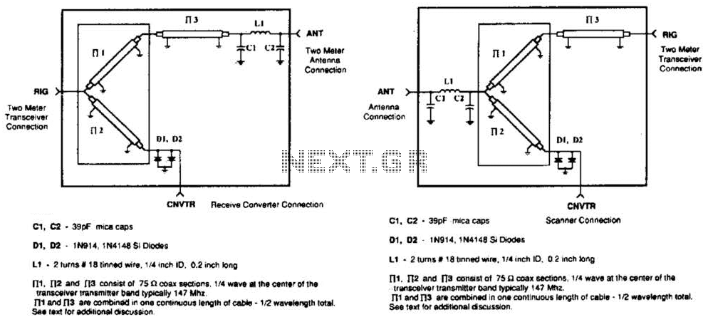
A pair of diodes and a quarter-wave transmission line are utilized as an automatic TR switch. D1 and D2 conduct during transmit periods, short-circuiting the scanner input. In this mode, the quarter-wave line appears as an open circuit. In...
When the phototransistor is struck by infrared (IR) light, it begins to conduct, causing the voltage across a 1 MΩ resistor (chosen arbitrarily) and the phototransistor to drop from VCC to lower values. When this voltage falls below VCC/3,...
This compact switching power supply utilizes a Schmitt trigger oscillator to control a switching transistor, which provides current to a small inductor. When the transistor is activated, energy accumulates in the inductor, and this energy is subsequently released into...
This circuit illuminates a lamp at a remote location when the doorbell switch is activated. It is designed exclusively for use with solenoid-type doorbells; electronic doorbells that produce melodies are not compatible. The circuit addresses the issue of potentially...
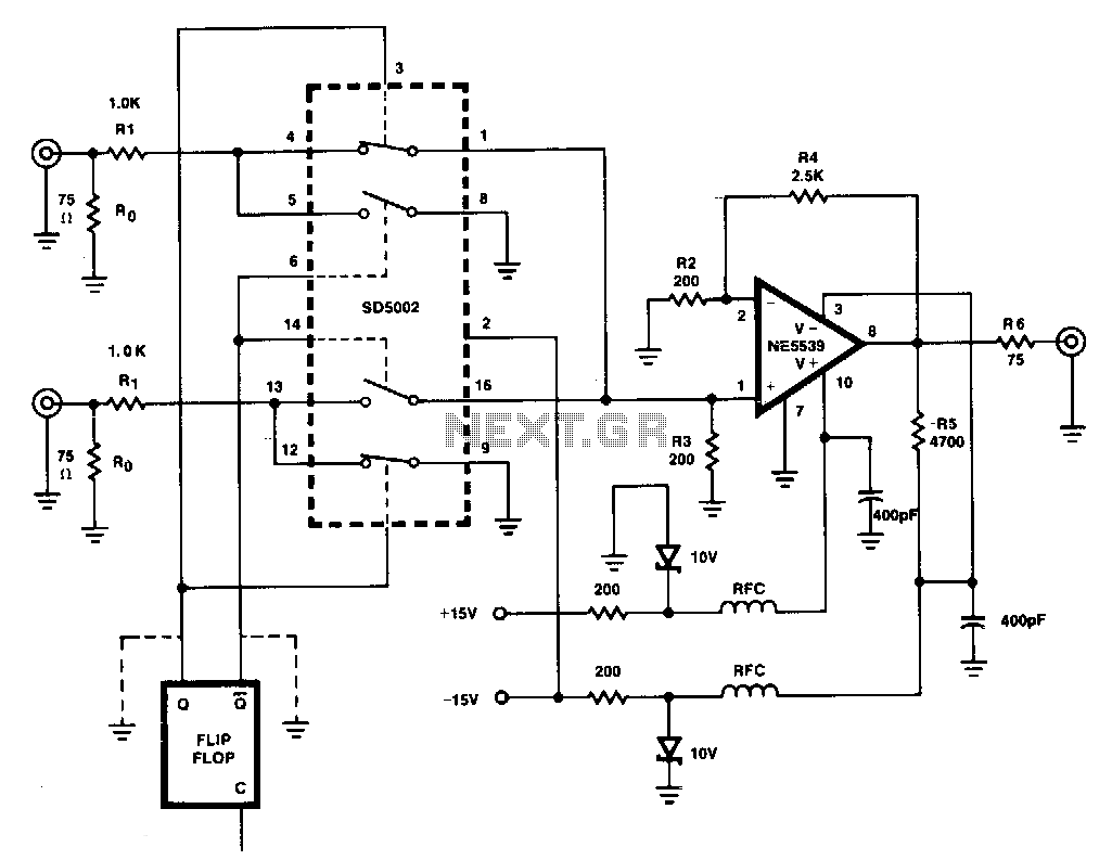
This figure illustrates a one-of-two switch featuring a summing amplifier. The video source's line can be terminated either externally or internally to switch RO. With this termination resistor, a load change of less than 10 ohms will be perceived...
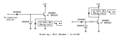
The two circuits illustrated show the operation of opening a relay contact shortly after the ignition or light switch is turned off. A capacitor is charged, and the relay remains closed until the voltage at the diode anode rises...
Warning: include(partials/cookie-banner.php): Failed to open stream: Permission denied in /var/www/html/nextgr/view-circuit.php on line 713
Warning: include(): Failed opening 'partials/cookie-banner.php' for inclusion (include_path='.:/usr/share/php') in /var/www/html/nextgr/view-circuit.php on line 713