
simple switch off time delay schematic
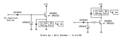
The two circuits presented serve to effectively manage the timing of relay activation in response to the ignition or light switch state. The common collector circuit, while simpler due to the absence of a series resistor, limits the voltage available to the relay coil, potentially affecting its performance during activation. In contrast, the common emitter circuit maximizes relay voltage, ensuring reliable operation, particularly in applications where the relay must operate within strict voltage parameters.
For practical implementation, the choice of components—specifically the capacitor and resistor—should be made with careful consideration of the relay specifications and the desired delay duration. The calculated values provide a solid foundation for selecting components, while adjustments may be necessary based on real-world testing. The use of a standard capacitor value, such as 1000 µF, simplifies sourcing components, and adjusting the resistor value allows for fine-tuning of the delay to meet specific requirements. Additionally, it is essential to ensure that the transistor selected can handle the required current and voltage levels, and that the diode used in the circuit is rated appropriately for the application to prevent damage and ensure reliable operation.The two circuits di atas illustrate opening a relay contact a short time after the ignition or ligh switch is turned off. The capacitor is charged and the relay is closed when the voltage at the diode anode rises to 12 volts.
The circuit on the left is a common collector or emitter follower and has the advantage of one less part since a resistor i s not needed in series with the transistor base. However the voltage across the relay coil will be two diode drops less than the supply voltage, or about 11 volts for a 12. 5 volt input. The common emitter configuration on the right offers the advantage of the full supply voltage across the load for most of the delay time, which makes the relay pull-in and drop-out voltages less of a concern but requires an extra resistor in series with transistor base.
The common emitter (circuit on the right) is the better circuit since the series base resistor can be selected to obtain the desired delay time whereas the capacitor must be selected for the common collector (or an additional resistor used in parallel with the capacitor). The time delay for the common emitter will be approximately 3 time constants or 3*R*C. The capacitor/resistor values can be worked out from the relay coil current and transistor gain. For example a 120 ohm relay coil will draw 100 mA at 12 volts and assumming a transistor gain of 30, the base current will be 100/30 = 3 mA.
The voltage across the resistor will be the supply voltage minus two diode drops or 12-1. 4 = 10. 6. The resistor value will be the voltage/current = 10. 6/0. 003 = 3533 or about 3. 6K. The capacitor value for a 15 second delay will be 15/3R = 1327 uF. We can use a standard 1000 uF capacitor and increase the resistor proportionally to get 15 seconds. 🔗 External reference
Related Circuits
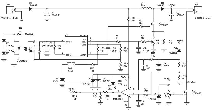
The Ultra Fast Battery Charger for Nickel-Cadmium (NiCad) battery cells is designed to efficiently charge NiCad batteries. This charger, referred to as the Ultra Fast NiCad Battery Charger, is capable of rapidly filling NiCad battery cells. The charger is...
This simple circuit combines two or more audio channels into a single channel (for example, mixing stereo into mono). The circuit is capable of mixing an arbitrary number of channels while consuming minimal power. Although the schematic illustrates two...
This circuit is constructed around a 555 timer and utilizes very few components. Due to its simplicity, even beginners can easily assemble and use it as a control device. A readily available laser pointer can be employed to operate...
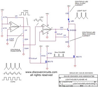
The aboriginal accessory forms a typical oscillator circuit that produces both a triangle waveform signal and a square wave signal. The triangle signal is fed into a voltage regulator circuit, which converts the triangle voltage signal to a triangle...
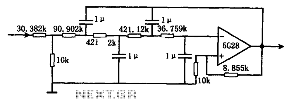
The circuit illustrated in the figure represents a staggered low-frequency active filter. This is a fourth-order Butterworth low-pass active filter designed to filter very low frequency (VLF) random pulse noise voltage at the DC level. The cut-off frequency is...
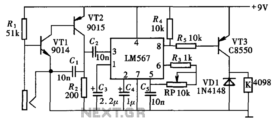
The electronic lock circuit is based on the frequency characteristics of the LM567 audio decoder. This circuit utilizes the audio decoding feature of the LM567, which outputs a low signal when the input signal frequency matches the oscillation frequency...