
Toggle Switch with 4013

The circuit utilizes a CMOS 4013 dual D-type flip-flop integrated circuit, specifically employing one half of the IC to achieve a toggle switch functionality. When a momentary push-to-make switch is pressed, it sends a brief high signal to the clock input of the flip-flop, causing it to toggle its output state. The output of the flip-flop is connected to the relay's coil, which controls the relay's operation.
The relay serves as an electromechanical switch, allowing for the control of higher power devices while being operated by the low power signal from the CMOS IC. The circuit can be powered by a voltage supply ranging from 5 to 15 volts, making it versatile for various applications. The choice of relay should be based on the coil voltage compatible with the selected supply voltage.
In addition to the relay, an LED can be integrated into the circuit for visual feedback, indicating the current state of the relay (energized or de-energized). The LED can be connected in parallel with the relay coil or in series with a current-limiting resistor to ensure proper operation without exceeding the LED's forward voltage rating.
The circuit design is straightforward and allows for the construction of two independent toggle switches by utilizing both halves of the CMOS 4013 chip, thereby providing an efficient solution for applications requiring multiple relay controls. Proper attention should be given to the relay's specifications, including its contact ratings and coil resistance, to ensure reliable operation within the intended application.This simple circuit will energize and de-energize a relay at the push of a button. Any type of momentary action push-to-make switch can be used. Pushing the button once - will energize the relay. And pushing it a second time - will de-energize the relay Only one half of the Cmos 4013 is used. So you could construct two independent toggle switches with a single IC. The circuit will work at anything from 5 to 15-volts. All you need do is select a relay with a coil voltage that suits your supply. The LED 🔗 External reference
Related Circuits
The project involves designing and constructing a breadboard power supply that draws power from an ATX-like switch-mode power supply (SMPS) using a 4-pin Molex connector. The design features a switch to select either a 12V or 5V output. However,...
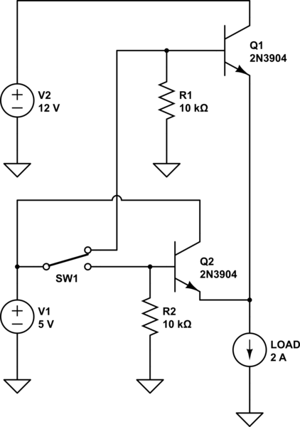
These circuits allow an ON-ON type DPDT toggle switch to control a twin coil switch machine motor. The handle of the switch can then be used to indicate the route selected. The circuits are also able to control LEDs...
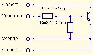
This is a straightforward guide to constructing a digital switch for a camera, enabling photo capture through microcontrollers. Required components include: 1. A digital switch for a camera can be implemented using a microcontroller, such as an Arduino or...
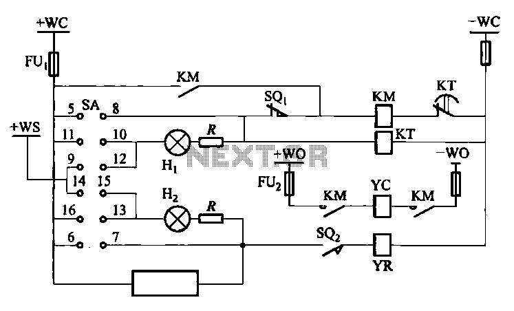
The DW10M de-excitation type switch is based on the DW10 automatic air circuit breaker, transitioning from normally open to normally closed contact. The models available include DW10M-200, DW10M-400, and DW10M-600. The control circuit for this type switch is illustrated...
This is a single-channel (on/off) universal switch that can be used with any infrared remote control operating within wavelengths of 850-950 nm. The single-channel universal switch functions as a simple on/off control mechanism, allowing users to operate electronic devices remotely...
This document outlines the layout considerations for switch-mode DC-DC converter printed circuit boards (PCBs) aimed at minimizing switching noise and electromagnetic interference (EMI). The layout of switch-mode DC-DC converter PCBs is critical in ensuring efficient operation and compliance with electromagnetic...