
Tone burst generator
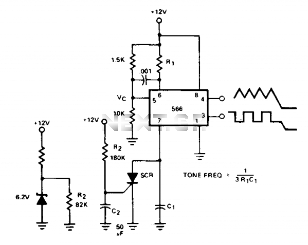
The tone burst generator circuit is designed to provide a reliable alert signal in communication networks. Upon activation, a timing mechanism initiates the generation of a tone for a precise duration of 0.5 seconds. The SCR plays a crucial role in controlling the cessation of the tone by diverting the current from the timing capacitor C1 once it is triggered. The timing capacitor C2 is integral to the triggering process, as it charges to a specific gate voltage necessary to activate the SCR.
To ensure the SCR functions correctly, it must be sensitive enough to trigger with the limited current of 70 µA. Adjusting R2 to a lower resistance can increase the triggering current, which may be necessary in scenarios where the SCR's sensitivity is inadequate. The potential adjustment of C2 is also important, as it helps maintain the desired time constant for the tone burst.
For applications requiring consistent tone duration across varying supply voltages, the integration of a Zener diode regulator circuit is advisable. This addition stabilizes the voltage supplied to the circuit, ensuring that the timing remains unaffected by fluctuations in the power supply. The adjustment of R2 to a new value of 82 kΩ is necessary to accommodate this change while preserving the circuit's functionality.
In cases where more flexible control of the tone is required, replacing the SCR with an NPN transistor offers an effective solution. This modification allows the tone to be turned on and off at will, providing greater control over the alert signal. The base terminal of the transistor serves as the control point, enabling rapid activation and deactivation of the tone burst as needed. This versatility can be particularly beneficial in dynamic communication environments where timely alerts are critical.The tone burst generator supplies a tone for one-half second after the power supply is activated; its intended use is a communications network alert signal. Cessation of the tone is accomplished at the SCR, which shunts the timing capacitor CI charge current when activated.
The SCR is gated on when C2 charges up to the gate voltage which occurs in 0.5 seconds. Since only 70 ?? are available for triggering, the SCR must be sensitive enough to trigger at this level. The triggering current can be increased, of course, by reducing R2 (and increasing C2 to keep the same time constant). If the tone duration must be constant under widely varying supply voltage conditions, the optional Zener diode regulator circuit can be added, along with the new value for R2 R2' = 82 kfi.
If the SCR is replaced by an npn transistor, the tone can be switched on and off at will at the transistor base terminal. 🔗 External reference
Related Circuits

The circuit utilizes two unijunction transistors. The low-frequency sawtooth generated by Q1 modulates the high-frequency tone produced by Q2. The output is designed to feed into a high-impedance amplifier. Both Q1 and Q2 are 2N4871 transistors. The circuit comprises two...
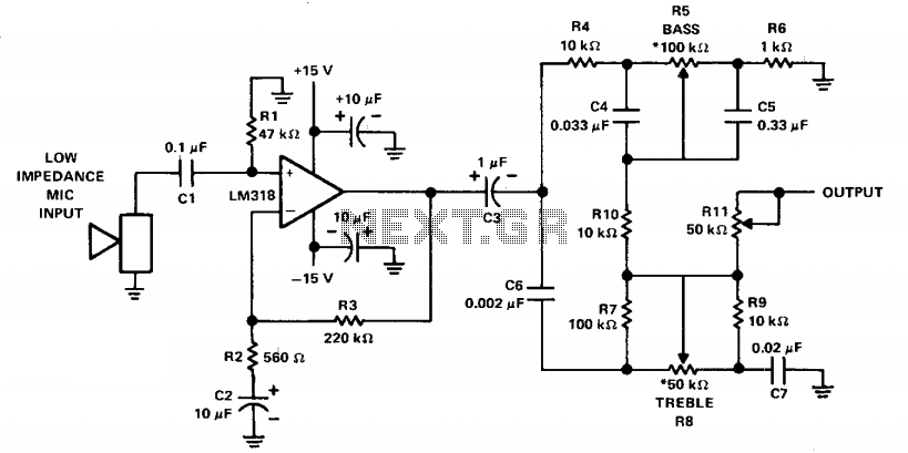
The LM318 operational amplifier is configured as a standard non-inverting amplifier. Resistor R1 (47 kΩ) provides a ground path for the bias current of the non-inverting input. The combination of R2 (560Ω) and C2 (10µF) creates a frequency roll-off...
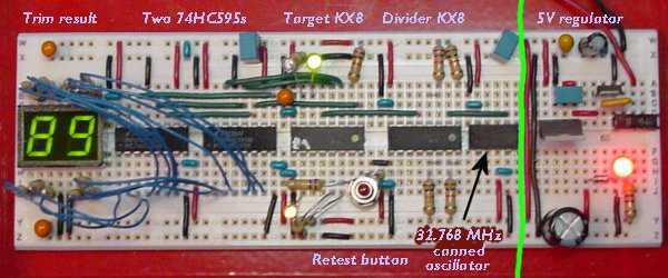
One of the nicest features of the 8-bit KX8 microcontroller (manufactured by Freescale Semiconductor) is that it includes an internal clock generator (ICG). This allows the chip to run without the trouble and expense of an external crystal or...
It is widely recognized that power-saving regulations necessitate very low power consumption during standby conditions for all equipment continuously connected to mains power. In the standard version of the power supply, standby power consumption is approximately 9.0 W for...
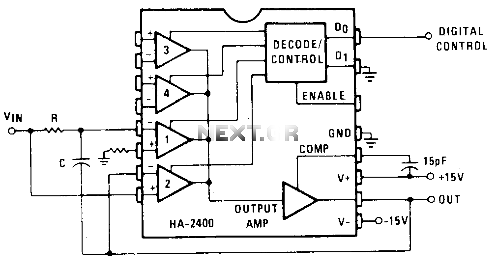
Channel 1 is configured as a conventional integrator, while Channel 2 is set up as a voltage follower. When Channel 2 is activated, the output will track the voltage of VJN, and capacitor C will discharge to maintain 0...
Descriptions of the various modules in a home-built music synthesizer - Sub-oscillator project. The sub-oscillator module in a home-built music synthesizer serves a crucial role in enriching the sound by generating lower frequency signals that complement the primary oscillators. This...