
Warbling tone generator

The circuit comprises two unijunction transistors (UJTs), specifically the 2N4871 model, which are employed to create a modulation effect between a low-frequency sawtooth waveform and a high-frequency tone. The first transistor, Q1, generates a low-frequency sawtooth signal, which serves as the control signal for the second transistor, Q2. The function of Q2 is to produce a high-frequency tone that is modulated by the signal from Q1.
In this configuration, the output of Q2 is intended to interface with a high-impedance amplifier. This amplifier is crucial for ensuring that the generated high-frequency tone is preserved without significant loss of signal integrity. The design emphasizes the need for high impedance to prevent loading effects that could distort the output signal.
The UJT operates by exploiting its unique characteristics, where the control of the emitter current through Q1 affects the timing and frequency of the oscillation in Q2. This interaction allows for the modulation of the high-frequency output based on the varying sawtooth waveform generated by Q1. The choice of the 2N4871 transistors is significant due to their suitable specifications for generating the desired frequency ranges and their reliability in oscillator applications.
Schematic considerations for this circuit would include the proper biasing of the UJTs, ensuring that they operate within their designated regions for optimal performance. Additionally, coupling capacitors may be employed at the output stage to maintain signal integrity while interfacing with the high-impedance amplifier. Overall, this circuit design effectively combines frequency modulation techniques with robust transistor characteristics to achieve a versatile output suitable for various electronic applications.The circuit use two unijunction transistors. The low-frequency sawtooth generated by Ql modulates the high-frequency tone generated by Q2. The output should feed into a high-impedance amplifier. Ql = Q2 = 2N4871. 🔗 External reference
Related Circuits
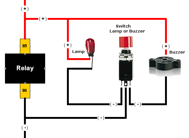
Upon acquiring the car, it was appreciated that it did not emit a "chirp" or sound the horn each time the doors were locked or unlocked. There are occasions when discreetness is preferred regarding entering or exiting the vehicle....
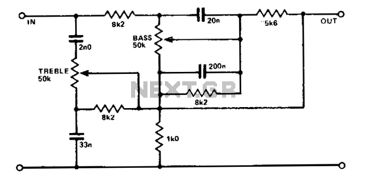
A simple circuit using two potentiometers and easily available standard value components provides tone control. The impedance level is suitable for low-level transistor or op-amp circuitry. This tone control circuit typically employs two potentiometers to adjust the bass and treble...
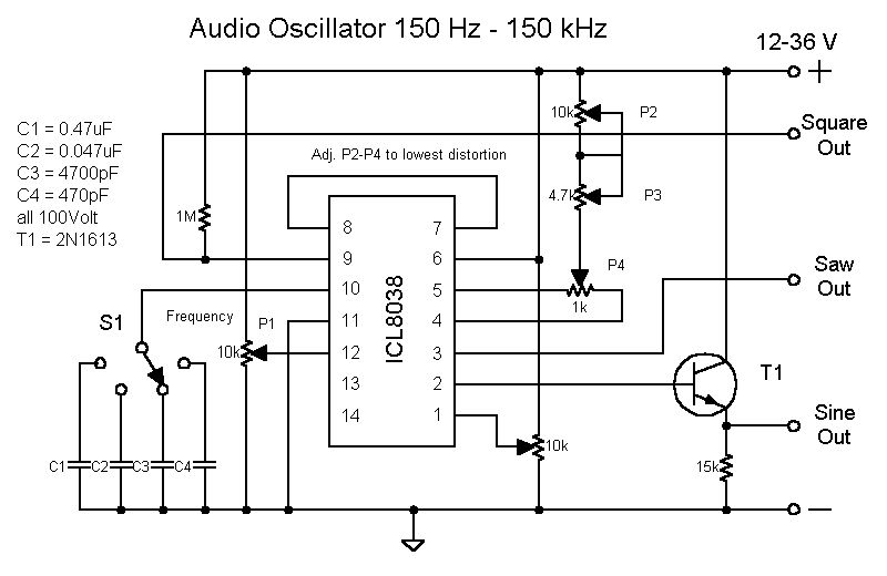
The circuit is straightforward, utilizing a single IC chip, the ICL8038 function generator chip, which produces simultaneous sine, square, and sawtooth waveforms. The circuit consists of a minimal number of components, including two resistors, one transistor, five trimpots, and...
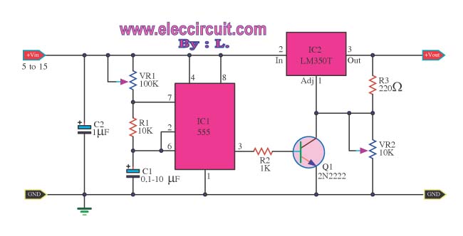
This is a Power Pulse Generator Circuit that utilizes the integrated circuit NE555 as a square wave oscillator generator. The frequency can be adjusted by varying resistor R1. The output from the NE555 is then sent to a transistor...
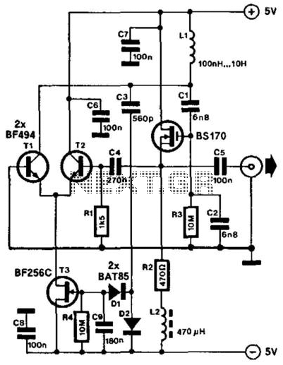
This compact LC oscillator operates within a frequency range of approximately 1 kHz to nearly 9 MHz and provides a low-distortion sine-wave output. The core of the circuit consists of a series-resonant circuit formed by inductor L1 and capacitors...
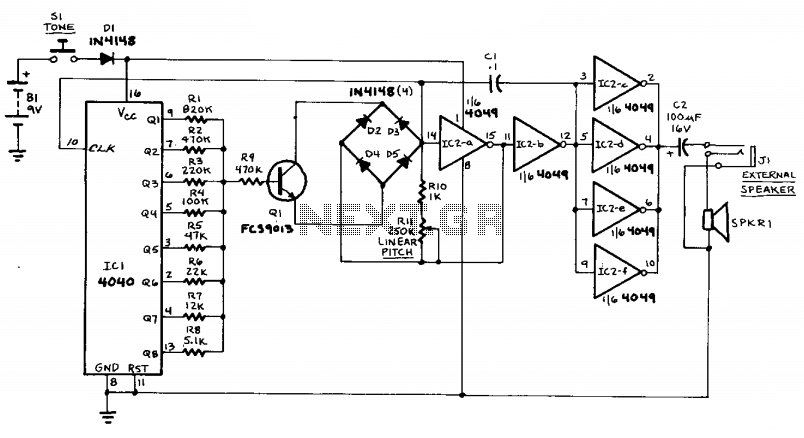
This circuit can generate sounds such as a European police-car siren, bird noises, and spaceship sounds. It can also function as a doorbell or an alarm. The circuit consists of four main components: a binary counter, a digital-to-analog (D/A)...