
Tone Control Circuit

The circuit described utilizes a BC109C transistor as a buffer stage, which is critical for maintaining high input impedance while minimizing loading effects on the preceding circuit. The transistor's configuration ensures that it does not significantly alter the signal amplitude, providing a voltage gain that is nearly unity. This characteristic is essential for preserving the integrity of the audio signal as it passes through the tone control section.
The Baxandall tone control circuit is characterized by its passive nature, meaning that it does not provide gain but instead manipulates the frequency response of the audio signal. This manipulation occurs through the use of capacitors and potentiometers, which allow for adjustments in bass and treble frequencies. The reactance of the capacitors, in conjunction with the settings of the linear potentiometers, determines how different audio frequencies are attenuated or emphasized, resulting in a tailored audio output that suits user preferences.
The final transistor stage is designed to provide a slight amplification of the audio signal, with an approximate gain of 3 times. This gain is beneficial for ensuring that the output signal is sufficiently strong to drive an amplifier. The output stage of the circuit is intended to interface with amplifiers that have input impedances ranging from 10k to 250k ohms, which is a common specification for audio equipment. This compatibility ensures that the circuit can effectively drive a variety of amplifiers without signal degradation.
In conclusion, the described circuit effectively combines buffering, passive tone control, and amplification to create a versatile audio processing solution. The use of linear potentiometers for tone control allows for precise adjustments, while the careful selection of transistor stages ensures that the audio signal remains robust throughout the processing chain.The first BC109C transistor (left hand side) is acting as a buffer. It provides the circuit with a high input impedance, around 250k has a voltage gain of slightly less than unity. As the Baxendall tone control circuit is a passive design, all audio frequencies are attenuated. The position of the controls and reactance of the capacitors alters the audio response. The last transistor provides a slight boost of about 3x. The output is designed to feed an amplifier with input impedance of 10k to 250k. Both tone controls should be linear type potentiometers. 🔗 External reference
Related Circuits
In a lithium-ion cell, a voltage of 3.8V per cell indicates a state of charge of approximately 50%. It is important to note that using voltage as a fuel gauge is not precise, as cells manufactured by different companies...
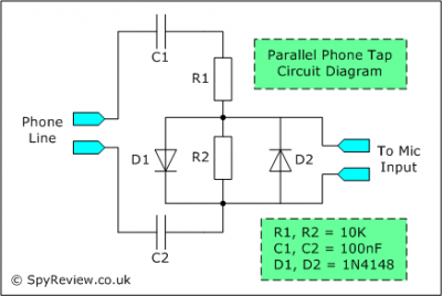
This file contains a schematic for a simple wiretap and instructions for connecting a small tape recorder control relay to the phone line. The discussion begins with an overview of various types of taps, including transmitters, wired taps, and...
This circuit is a differential analog switch circuit utilizing the FM1208 monolithic dual differential multiplexer. It is designed for applications where the on-resistance (RDS(ON)) must match closely. The RDS(ON) for the monolithic dual multiplexer exhibits better than 1% accuracy...
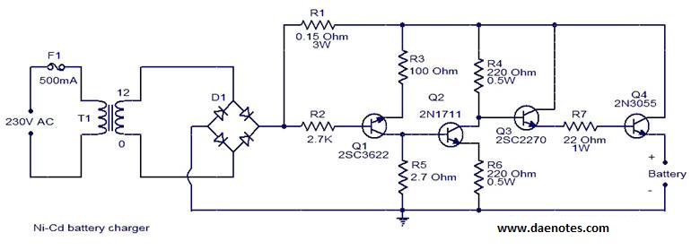
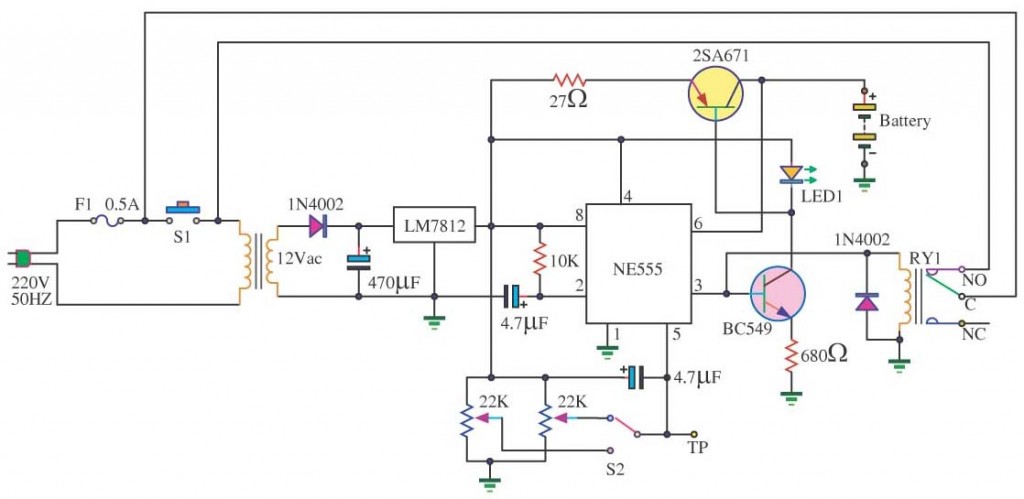
This circuit is primarily designed for charging 12V Ni-Cd battery packs. However, it can also be used to charge 6V and 9V battery packs with slight modifications. The circuit operates by utilizing a power supply that provides the necessary voltage...
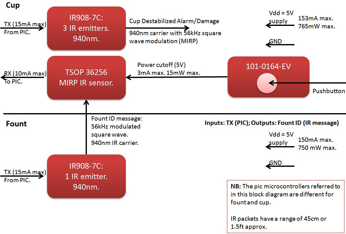
The founts must notify the server when the cup is taken from the fount or when the opponent's cup is poured into the team's cup. The implementation of the actual pouring action is at the discretion of the team....
This circuit is an Infra-Red Remote Control Tester designed to verify the functionality of any remote control that transmits infrared (IR) light. It operates on a 3V battery and offers several advantages, such as its compact size and the...