
74HC11 Infra-Red Remote Control Tester
This Infra-Red Remote Control Tester circuit is a straightforward yet effective tool for determining the operational status of remote controls. The circuit's core component, the Schmitt trigger gate, provides a stable output by converting the varying input signals from the IRED into a clean digital signal. The IRED emits infrared light when activated, which is detected by the remote control. The pulse bursts from the remote are captured by the circuit, which then processes these signals.
The R-C network at the output serves a dual purpose. Firstly, it smooths out the pulse signals, ensuring that the output remains stable while the remote is in operation. Secondly, the additional R-C network prevents false triggering of the output LED, which could occur due to ambient IR light sources. This feature is particularly useful in environments with significant background IR interference, such as those illuminated by sunlight or other IR-emitting devices.
In terms of construction, the circuit can be assembled on a small printed circuit board (PCB) or a breadboard, allowing for easy prototyping and testing. The choice of components is critical; therefore, it is recommended to use a high-quality IRED and a reliable Schmitt trigger IC to ensure consistent performance. The LED indicator (D2) provides a visual confirmation of the remote's operation, lighting up only when the correct IR signals are detected.
Overall, this Infra-Red Remote Control Tester circuit exemplifies an efficient design that balances simplicity, cost-effectiveness, and functionality, making it an excellent tool for both hobbyists and professionals in the field of electronics.This is Infra-Red Remote Control Tester circuit. This circuit is used to test go/no-go of any remote control transmitting infra-red (IR) light. The supply of this circuit is 3V battery. This circuit has some advantages, such as fits in a compact enclosure, built from inexpensive parts and a handful of commonly available. As a quasi-analogue amplif ier, this circuit uses Schmitt trigger gate IC1f with the sensor element. The sensor element is an infra-red emitting diode (IRED) type LD274. All IR remote controls transmit pulse bursts, so an R-C network, C1-R2, is used at the output of the gate. Beside that, An R-C network is also used to prevent the output LED, D2, lighting constantly when another continuous source of IR light or day-light is detected.
[Circuit`s schematic diagram source: extremecircuits. net] We aim to transmit more information by carrying articles. Please send us an E-mail to wanghuali@hqew. net within 15 days if we are involved in the problems of article content, copyright or other problems. We will delete it soon. 🔗 External reference
Related Circuits
S1 and S2 are normally open, push-to-close, momentary switches. The diodes can be either red or green and are used solely for indicating direction. The TIP31 transistors may need to be adjusted based on the motor specifications. It is...
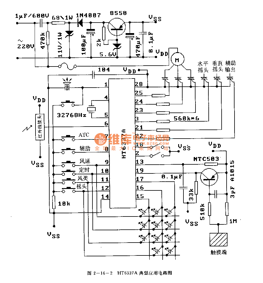
The HT6337 is an infrared remote control receiving decoder circuit specifically designed for electric fan applications. It is housed in a 28-pin dual-row DIP package, with the compatible model being HT12C. The HT6337 is part of a series of...
AC power is supplied through AC Fuse F1 and Power On/Off switch S1 to a 6.3V filament transformer T1. An additional safety feature, Fuse F2, is included, as a short circuit to the filament transformer may not trigger the...
A photodiode, SFH2030, serves as an infrared sensor. A MOSFET operational amplifier, CA3140, is utilized in differential mode to amplify the current pulses from the photodiode. LED1, an ordinary colored LED, illuminates when infrared radiation is detected. The output...
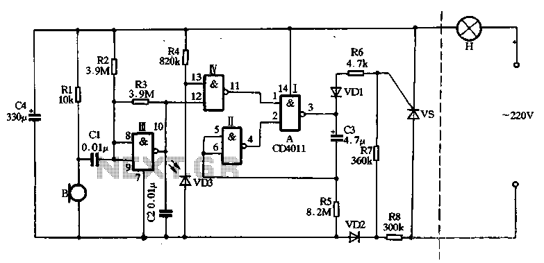
The main circuit utilizes a two-input NAND gate composed of four digital integrated circuits. This includes a NAND gate microphone amplifier circuit, a light control mechanism using an "AND gate," and a monostable delay control circuit formed by NAND...

The low output impedance of a closed-loop operational amplifier (op amp) provides ideal immunity to line noise, while the offset voltage drift of the op amp serves as a temperature sensor. Utilizing the op amp in this manner requires...
Warning: include(partials/cookie-banner.php): Failed to open stream: Permission denied in /var/www/html/nextgr/view-circuit.php on line 713
Warning: include(): Failed opening 'partials/cookie-banner.php' for inclusion (include_path='.:/usr/share/php') in /var/www/html/nextgr/view-circuit.php on line 713