
Thermometer circuit schematic using operational amplifiers
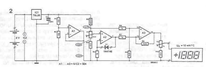
The described thermometer circuit employs operational amplifiers to create a temperature sensing device that is both simple and effective. The operational amplifier configuration allows for precise measurement of the diode's voltage drop, which varies with temperature. The diode acts as a temperature sensor, where its forward voltage drop decreases as temperature increases. This relationship is exploited in the circuit design, allowing for a linear output voltage that correlates to temperature readings.
The non-inverting input of amplifier A3 is stabilized using a voltage divider formed by R3, P1, and R4, ensuring that the reference voltage remains constant despite variations in supply voltage or temperature. The choice of resistors R6 and R8 is critical, as they define the scale of the output voltage in relation to temperature, specifically calibrating the circuit to output 0 V at 0 °C. The use of a voltage regulator (IC1) is essential for maintaining a stable reference voltage, particularly when measuring temperatures that fall below or above the freezing point, as it allows the circuit to operate without a dual power supply.
Amplifier A1, along with resistors R1 and R2, generates a reference voltage of 2.5 V, which serves as a midpoint reference for the operational amplifiers in the circuit. This design choice facilitates the use of a single power supply and simplifies the overall circuit architecture. Calibration is performed using potentiometers P1 and P2, allowing the user to fine-tune the output voltage to match the desired temperature readings accurately.
In summary, this thermometer circuit is a practical application of operational amplifiers and diodes, providing a straightforward method for temperature measurement with a clear linear output. The design emphasizes stability and ease of calibration, making it suitable for various applications where temperature monitoring is required.A simple thermometer built with operational amplifiers and a normal or protective diode such as 1N4148, instead of the temperature sensor can be made using electronic diagram below. A constant reference voltage is applied to the noninverting input of operational amplifier. Current passing through the diode, is also maintained at a constant level. Variations in operational amplifier output voltage can appear only as a result of a change in diode voltage drop and this, in turn, can be caused only by variations in temperature. The output voltage is directly proportional to the diode temperature. Noninverting input of A3 is maintained at a constant level (also obtained with R3 / P1 / r4) and the values of R6 and R8 were chosen so that 0 V to correspond to an ambient temperature of 0 degrees C.
In order to measure above and below zero without the use of a symmetrical supply is necessary to use a regulator IC1, A2 and A3 for generating a reference voltage steady enough. An additional amplifier, A1, together with R1 and R2, generates a voltage of 2. 5 V relative to the negative power bar. These are then used as 2. 5 V for the rest of the circuit board. If you need a continuous, you must use a single power source, for IC1 does not need to be stabilized.
The circuit is calibrated by adjusting P1 IUI, to obtain 0 V at 0 ° C, and then P2, to get 0. 999 V to 99. 9 ° C 🔗 External reference
Related Circuits
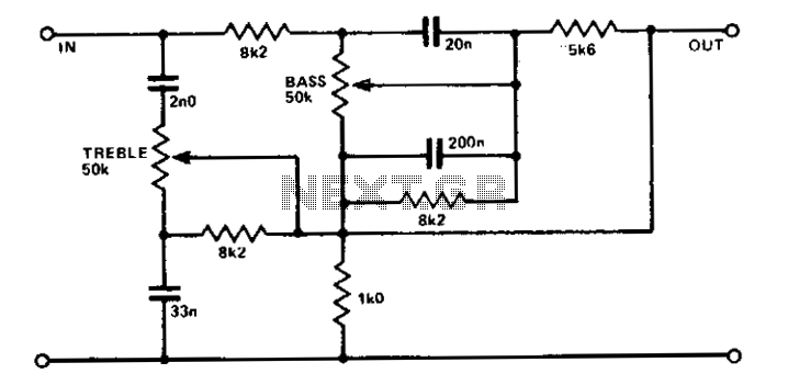
A simple circuit using two potentiometers and easily available standard value components provides tone control. The impedance level is suitable for low-level transistor or op-amp circuitry. This tone control circuit typically employs two potentiometers to adjust the bass and treble...
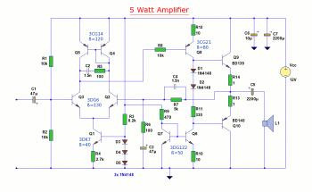
The diagram illustrates a 5W audio amplifier circuit constructed using power transistors BD139 and BD140 for the final amplification stage. This compact amplifier serves as a general-purpose amplifier suitable for applications such as computer audio, radio, MP3 players, and...
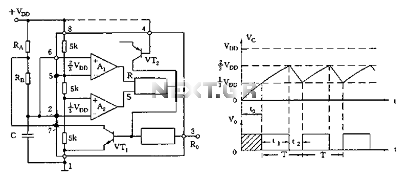
The circuit diagram illustrates the 555 timer (or 556 timer in half configuration) configured in astable multivibrator mode. It features three resistive and capacitive elements connected as shown. In one-shot mode, the trigger terminal (pin 2) is connected to...

The circuit utilizes a tuned circuit for frequency selection, designed to operate at approximately 51 kHz. The 2N3565 transistor amplifies the output generated by the tuned circuit. The described circuit operates on the principle of resonance, where the tuned circuit...
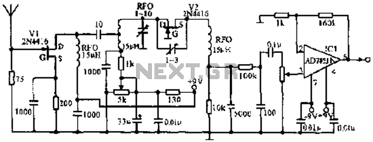
The image illustrates the JFET VHF band super-regenerative receiver circuit. It features high discharge tubes V1 and V2, which serve as the super-regenerative detector tubes. IC1 functions as a low-frequency amplifier. The circuit exhibits a sensitivity of better than...
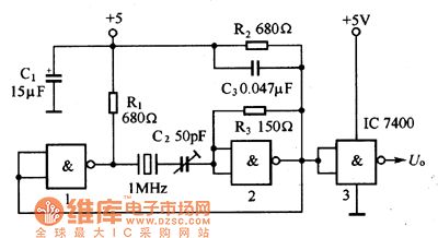
The oscillator circuit consists of a 1MHz quartz crystal resonator and a NAND gate, with the output buffer stage provided by NAND gate 3. This circuit can be utilized for calibrating standard frequency. The described oscillator circuit operates at a...