
0-30 VDC Stabilized Power Supply with Current Control 0.002-3 A
The circuit design employs a step-down transformer, rectification, and filtering to convert AC mains voltage into a stable DC output. The use of a bridge rectifier ensures efficient conversion with minimal ripple, while the filtering components (C1 and R1) smooth the output for reliable performance. The unique constant gain amplifier configuration not only stabilizes the output voltage but also provides a robust reference voltage, ensuring consistent operation across varying load conditions.
The incorporation of a current limiting feature enhances the circuit's versatility, allowing it to function as a constant current source when needed. This is particularly useful in applications where the load may vary significantly, ensuring that the output current remains within safe limits to protect both the power supply and connected devices. The ability to adjust the current limit provides an additional layer of control, making this power supply suitable for a wide range of applications, from laboratory setups to sensitive electronic devices.
Overall, the circuit is designed for both efficiency and reliability, with careful consideration given to component selection and configuration to ensure optimal performance across its operational range. The visual indicator provided by the LED offers immediate feedback on the current limiting status, enhancing user awareness and safety during operation.To start with, there is a step-down mains transformer with a secondary winding rated at 24 V/3 A, which is connected across the input points of the circuit at pins 1 & 2. (the quality of the supplies output will be directly proportional to the quality of the transformer).
The AC voltage of the transformers secondary winding is rectified by the bri dge formed by the four diodes D1-D4. The DC voltage taken across the output of the bridge is smoothed by the filter formed by the reservoir capacitor C1 and the resistor R1. The circuit incorporates some unique features which make it quite different from other power supplies of its class.
Instead of using a variable feedback arrangement to control the output voltage, our circuit uses a constant gain amplifier to provide the reference voltage necessary for its stable operation. The reference voltage is generated at the output of U1. The circuit operates as follows: The diode D8 is a 5. 6 V zener, which here operates at its zero temperature coefficient current. The voltage in the output of U1 gradually increases till the diode D8 is turned on. When this happens the circuit stabilises and the Zener reference voltage (5. 6 V) appears across the resistor R5. The current which flows through the non inverting input of the op-amp is negligible, therefore the same current flows through R5 and R6, and as the two resistors have the same value the voltage across the two of them in series will be exactly twice the voltage across each one.
Thus the voltage present at the output of the op-amp (pin 6 of U1) is 11. 2 V, twice the zeners reference voltage. The integrated circuit U2 has a constant amplification factor of approximately 3 X, according to the formula A=(R11+R12)/R11, and raises the 11. 2 V reference voltage to approximately 33 V. The trimmer RV1 and the resistor R10 are used for the adjustment of the output voltages limits so that it can be reduced to 0 V, despite any value tolerances of the other components in the circuit.
Another very important feature of the circuit, is the possibility to preset the maximum output current which can be drawn from the p. s. u. , effectively converting it from a constant voltage source to a constant current one. To make this possible the circuit detects the voltage drop across a resistor (R7) which is connected in series with the load.
The IC responsible for this function of the circuit is U3. The inverting input of U3 is biased at 0 V via R21. At the same time the non inverting input of the same IC can be adjusted to any voltage by means of P2. Let us assume that for a given output of several volts, P2 is set so that the input of the IC is kept at 1 V.
If the load is increased the output voltage will be kept constant by the voltage amplifier section of the circuit and the presence of R7 in series with the output will have a negligible effect because of its low value and because of its location outside the feedback loop of the voltage control circuit. While the load is kept constant and the output voltage is not changed the circuit is stable. If the load is increased so that the voltage drop across R7 is greater than 1 V, IC3 is forced into action and the circuit is shifted into the constant current mode.
The output of U3 is coupled to the non inverting input of U2 by D9. U2 is responsible for the voltage control and as U3 is coupled to its input the latter can effectively override its function. What happens is that the voltage across R7 is monitored and is not allowed to increase above the preset value (1 V in our example) by reducing the output voltage of the circuit.
This is in effect a means of maintaining the output current constant and is so accurate that it is possible to preset the current limit to as low as 2 mA. The capacitor C8 is there to increase the stability of the circuit. Q3 is used to drive the LED whenever the current limiter is activated in order to provide a visual indicat
🔗 External reference
Related Circuits
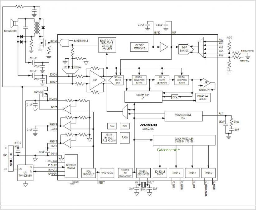
The MC33411 900 MHz Analog Cordless Phone Baseband system is designed to meet the specifications of a 900 MHz Analog cordless telephone system. It includes three Phase-Locked Loops (PLLs). Two of these PLLs are intended for use with external...
These photos were made in the years 1956 and 1957. On photo nr. 3, on the right, at the bottom, is the GMD. The work that was done at the objekt was of course top secret. It was strictly...
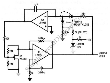
This is a quartz-stabilized oscillator circuit with electronic gain control. Replacing the common filament lamp for amplitude stabilization, this circuit uses... This circuit represents a quartz-stabilized oscillator featuring electronic gain control, which enhances the stability and precision of the output...
This circuit below shows a teleremote circuit that enables the switching on and off of appliances through telephone lines. The teleremote circuit utilizes a telephone line as a medium for controlling electrical appliances from a distance. The primary components...
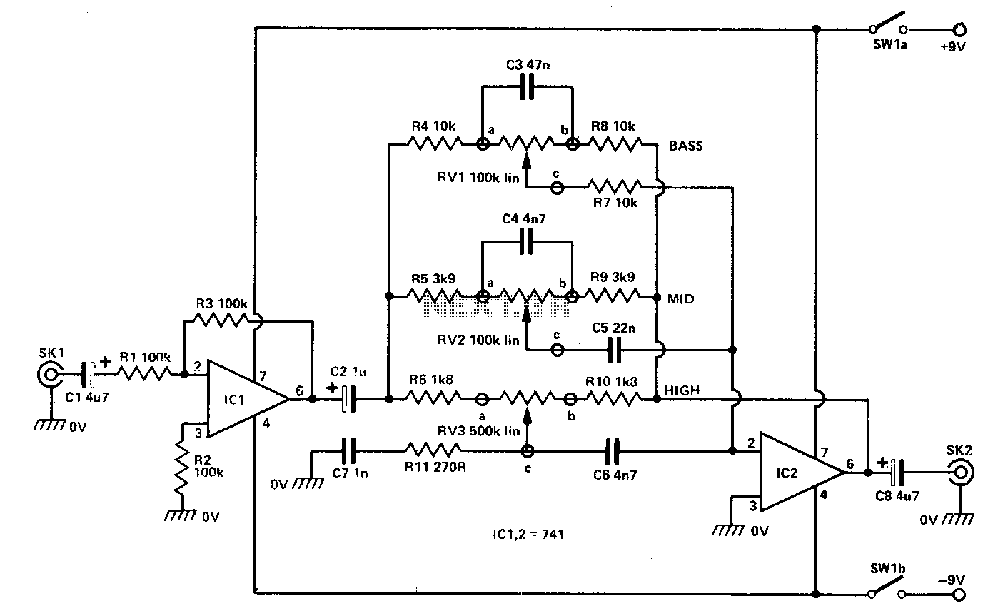
The input signal is fed through SKI to the first active stage, which is constructed around IC1. This stage is configured as a non-inverting amplifier, with its gain determined by the ratio of R3 and R1. In this configuration,...
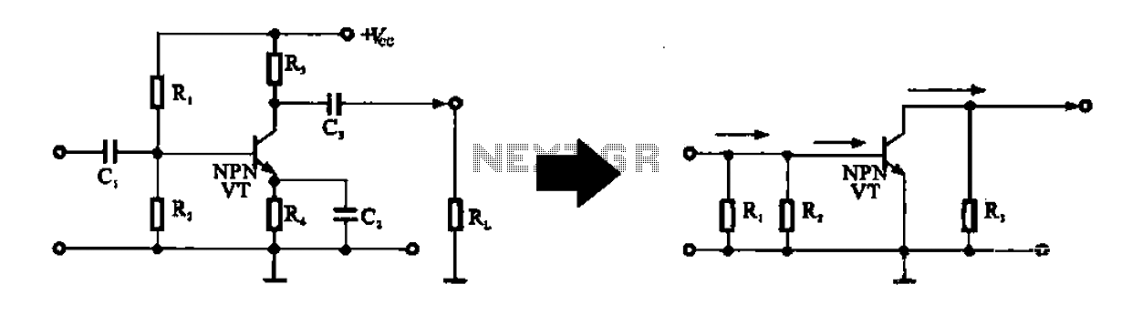
An alternating current voltage amplifier transistor AC path is described. In AC analysis, the internal resistance of the AC supply voltage source is low, which corresponds to a short circuit signal. Consequently, the alternating voltage terminal Vcc is considered...
Warning: include(partials/cookie-banner.php): Failed to open stream: Permission denied in /var/www/html/nextgr/view-circuit.php on line 713
Warning: include(): Failed opening 'partials/cookie-banner.php' for inclusion (include_path='.:/usr/share/php') in /var/www/html/nextgr/view-circuit.php on line 713