
tone controller circuit diagram two transistor
The two-transistor tone controller circuit operates effectively by leveraging the characteristics of each transistor to manipulate audio signals. The Q1 transistor serves as a buffer, allowing the circuit to maintain high input impedance while delivering adequate current to the subsequent stage. This configuration reduces loading effects on the audio source, ensuring that the integrity of the signal is preserved.
The second transistor, Q2, is configured to amplify the voltage level of the audio signal, facilitating further processing or output to a speaker or other audio device. The interaction between Q1 and Q2 is crucial; the emitter follower configuration of Q1 ensures that the output signal remains stable and faithful to the input signal, while Q2 provides the necessary gain to achieve the desired audio levels.
The tone control aspect of the circuit is realized through a carefully designed network of resistors and capacitors that connect the emitter of Q1 to the base of Q2. This network allows for the adjustment of frequency response, enabling users to tailor the audio output to their preferences. By varying the resistance and capacitance values, users can boost or attenuate specific frequency ranges, enhancing the listening experience.
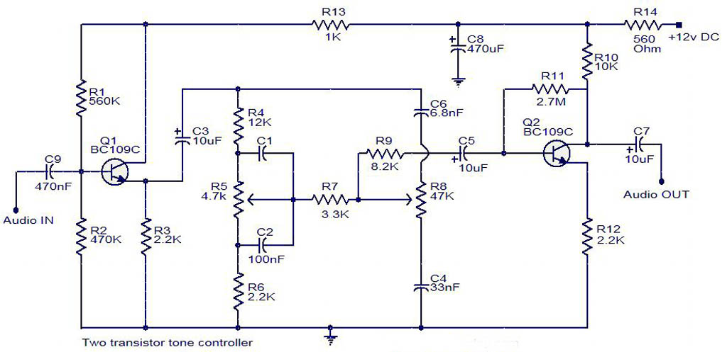
Overall, this tone controller circuit exemplifies a practical application of transistor technology in audio processing, illustrating how fundamental electronic components can be arranged to achieve complex functionalities in sound engineering.Electrical schematics diagram shown below is a simple two transistor tone controller audio circuit free pictures for download. This electric circuit is based on the well-known Baxandal tone control plan. Deviation in the value of these electrical circuit transistor components varies the audio response of the system.
This tone controller circuit ab le to present a highest attenuation and boost of 10decibel on 10 KHz/60 Hz frequency ranges. The first transistor Q1 (C828) is energetic an emitter follower to supply sufficient current gain and input impedance. The second transistor Q2 (C828)is used to voltage amplify the signal in. The network of resistance and capacitors connected connecting emitter of Q1 and base of Q2 is used to control the tone.
🔗 External reference
Related Circuits
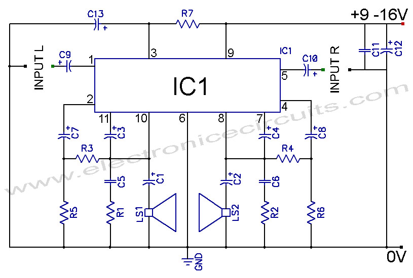
This volume controller equalizer electronic project utilizes the LM1036 DC tone volume controller, which includes a volume and balance circuit suitable for stereo applications. The LM1036 features an additional control input that facilitates simple loudness compensation. It provides four...
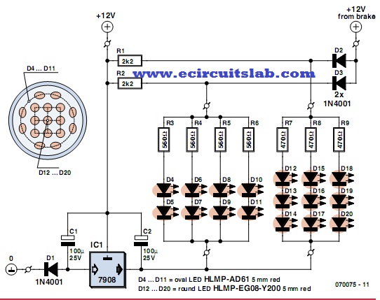
LEDs are increasingly utilized in motor vehicles, replacing traditional incandescent lamps due to their superior energy efficiency and extended lifespan. This article outlines a straightforward LED tail light specifically designed for motorcycles, scooters, and mopeds. There is a notable...
The IRF820 MOSFET has a voltage rating of 500V; it should work well in preamp stages of most tube amps. The 100-ohm resistor is there to suppress H.F. oscillations. If the IRF820 is physically close to the 12AX7 plate,...
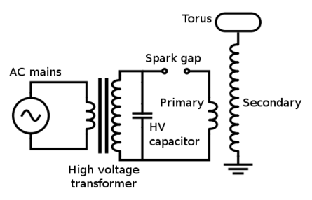
The Tesla Coil will utilize a high voltage (HV) power source that outputs 9 kV at approximately 30 mA. The construction of the Tesla coil includes six glass bottles, table salt, oil, and aluminum foil for the capacitors. The...
TDA2004 Car Battery 12W Stereo Amplifier Circuit. Its main features are low distortion, low noise, and high reliability of the chip. The TDA2004 is a highly integrated audio amplifier designed specifically for automotive applications. This circuit is capable of delivering...
A simple and cost-effective TV antenna amplifier circuit is constructed using the BF961, a dual-gate N-channel MOSFET, which serves as the input and mixer stages. The described TV antenna amplifier circuit utilizes the BF961 dual-gate N-channel MOSFET due to its...
Warning: include(partials/cookie-banner.php): Failed to open stream: Permission denied in /var/www/html/nextgr/view-circuit.php on line 713
Warning: include(): Failed opening 'partials/cookie-banner.php' for inclusion (include_path='.:/usr/share/php') in /var/www/html/nextgr/view-circuit.php on line 713