
Tube circuits for Guitar Amplifiers


This circuit is a "cascode." It is capable of high gain, is very linear, and is non-microphonic. A comparison to triode: JFET Source = Cathode; JFET gate = Grid; MOSFET Drain = Plate. The MOSFET is wired as a simple voltage regulator. The 1M resistor, zener, and 10µF cap set the reference voltage. Use a 24V or less zener. A signal applied to the "grid" causes the current through the JFET, MOSFET, and 100k "plate" resistor to vary. The output is tapped off the "plate" resistor, like a normal tube gain stage. Select a value for Rs that sets the "plate" voltage at approximately 50% of the supply voltage. Try typical 12AX7 cathode resistor values. Check the gain. If you want more gain, add bypass cap Cb. If that gives too much gain, put resistor Rb in series with the bypass cap. The value of the bypass cap can be used for tone shaping, as in a triode stage. The "plate" resistor can be varied over a wide range similar to 12AX7. The output cap can be varied for tone shaping purposes. This circuit works well as a first gain stage or a reverb return amplifier. No heatsink is required for the IRF820 in this configuration.
This is similar to the High Voltage Solid State Preamp stage, with the following exceptions: The "plate" load is a standard Fender-style reverb transformer. The "cathode" is unbypassed. The zener value has been reduced to 4.7V. The zener is tied to the "cathode" instead of ground. This allows a fairly large input signal to pass through relatively clean. This circuit can be inserted anywhere you would put the standard 12AT7-based circuit. A small heatsink is required for the IRF820. Remember that the heatsink is connected to the MOSFET Drain and has high voltage on it.
The IRF820 MOSFET serves as a critical component in this high-voltage preamplifier circuit, designed to operate efficiently in the signal path of tube amplifiers. It is essential to ensure that the IRF820 is utilized within its specified voltage rating of 500V, allowing it to handle the high voltages typically found in tube amplifier applications. The circuit employs a cascode configuration, enhancing linearity and gain while minimizing microphonic effects, which are often problematic in audio applications.
The arrangement of the MOSFET in relation to the tube components is crucial. The source of the MOSFET acts as the cathode, the gate corresponds to the grid, and the drain functions as the plate. This equivalence allows for a seamless integration of solid-state components within a traditionally tube-based circuit. However, it is important to note that the IRF820 does not self-bias, necessitating careful attention to biasing methods, particularly when setting the cathode resistor values.
The inclusion of a 100-ohm resistor aids in suppressing high-frequency oscillations, which can be detrimental to circuit performance. While this resistor may not be necessary if the IRF820 is positioned close to the 12AX7 plate, it can provide additional stability in other configurations. The circuit's design permits the use of a Zener diode for voltage regulation, with the recommended Zener voltage being 4.7V, ensuring that the reference voltage is stable and reliable.
The output stage, tapped from the plate resistor, allows for signal extraction similar to conventional tube stages. The flexibility in selecting the plate resistor value and bypass capacitor enhances the circuit's versatility, enabling tone shaping and gain adjustments to suit various applications. The circuit is well-suited for use as a first gain stage or in reverb applications, demonstrating its adaptability in different audio contexts.
In summary, this preamp circuit utilizing the IRF820 MOSFET is a sophisticated solution for integrating solid-state technology into tube amplifier designs, offering high gain, linearity, and the potential for tone shaping while maintaining the unique characteristics of tube amplification.The IRF820 MOSFET has a voltage rating of 500v, it should work well in preamp stages of most tube amps. The 100 ohm resistor is there to suppress H.F. oscillations. If IRF820 is physically close to the 12AX7 plate, you probably won't need it. You can see how the MOSFET is equivalent to a triode: Source = Cathode; Gate = Grid; Drain = Platel You cannot use the MOSFET as a directreplacement for a typical tube gain stage.
The MOSFET will not "self bias" like a typical cathode-biased tube stage.The MOSFET is an "enhancement device" while a triode is a "depletion" device. l In this circuit, it is not necessary to use a heatsink on the IRF820. You can if you want This circuit is a "cascode". It is capable of high gain, is very linear and is nonmicrophonic. l A comparison to triode: JFET Source = Cathode; JFET gate = grid; MOSFET Drain = Plate. l The MOSFET is wired as a simple voltage regulator. The 1M resistor, zener and 10uf cap set the reference voltage. Use a 24v or less zener. l A signal applied to the "grid" causes the current through the JFET, MOSFET and 100k "plate" resistor to vary. The output is tapped off the "plate" resistor, like a normal tube gain stage. l Select a value for Rs that sets the "plate" voltage at approximately 50% of the supply voltage.
Try typical 12AX7 cathode resistor values. Check the gain. If you want more gain, add bypass cap Cb. If that gives too much gain, put resistor Rb in series with bypass cap. The value of bypass cap can be used for tone shaping, as in triode stage. l The "plate" resistor can be varied over a wide range similar to 12AX7. The output cap can be varied for tone shaping purposes. l This circuit works well as a 1st gain stage, or a reverb return amplifier. l No heatsink is required for the IRF820 in this configuration. This is similar to the High Voltage Solid State Preamp stage, with the following exceptions: l The "plate" load is a standard Fender-style reverb transformer. l The "cathode" is unbypassed. l The zener value has been reduced to 4.7v l The zener is tied to the "cathode" instead of ground.
This allows a fairly large input signal to pass through relatively clean. l This circuit can be inserted anywhere you would put the standard 12AT7- based circuit. l A small heatsink is required for the IRF820. Remember that the heatsink is connected to the MOSFET Drain and has high voltage on it. 🔗 External reference
Related Circuits
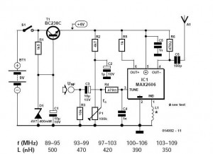
These do-it-yourself FM transmitters are relatively simple to construct and provide a satisfying experience when music is played through the radio receiver. Comments and links to additional designs that are not included in the best list are welcome. FM transmitters...
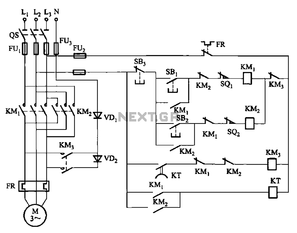
The circuit depicted in Figure 3-147 utilizes a time relay (KT) adjustable between 1 to 2 seconds to ensure adequate braking time. The relay addresses instances where the actual brake stop time may be insufficient. Additionally, SQ1 and SQ2...
A 40-watt fluorescent tube lamp or two 20-watt tubes in series will be driven by this circuit. The transformer is wound on a ferrite rod with a diameter of 10 mm and a length of 8 cm. The circuit described...
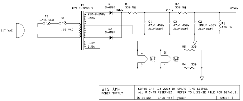
The PCB for this amplifier can be purchased from Spare Time Gizmos for $16 US. In a single afternoon, the entire board can be assembled and placed into a chassis of choice. The value and type of components are...
An integrated circuit is precisely that: an integrated circuit. These small packages combine numerous individual components to perform a specific function. They vary in shape and size depending on their complexity. They are categorized into functions such as audio,...
Activated this and inadvertently destroyed several 2N3055 transistors by shorting the emitters to ground. In all cases, the transistors opened up, and no damage to the emitter occurred in any transistor. The alternative circuit in Figure 2 will provide...