
TONE DISPLAY
The circuit utilizes the LM3914 integrated circuit, which is designed to drive a series of LEDs to visually represent an analog voltage. The device is capable of operating in two modes: "dot" mode, where only one LED is illuminated at a time, and "bar" mode, where all LEDs up to the current level are lit. This flexibility allows for a variety of visual feedback options depending on the application requirements.
To implement the tone display, the circuit first receives an analog control voltage that corresponds to the frequency of the tone being measured. This voltage is typically generated by a frequency-to-voltage converter or a similar circuit that translates frequency changes into a proportional voltage. The LM3914 then processes this voltage and drives the connected LEDs accordingly.
The ability to program the endpoints allows for customization of the display range. For instance, if the application requires displaying frequencies from 20 Hz to 20 kHz, the endpoints can be set to correspond to these values. The LM3914's reference voltage pins can be adjusted to set these limits, enabling precise control over the display.
Chaining multiple LM3914 devices is feasible, allowing for extended displays beyond the ten LEDs that a single unit can drive. This is accomplished by connecting the output of one LM3914 to the input of the next, creating a cascading effect. Each additional driver can be configured to represent a wider range of frequencies, effectively expanding the display capacity without loss of resolution.
The logarithmic scaling of the display is particularly important in musical applications, as musical notes are spaced logarithmically. Each octave represents a doubling of frequency, and thus the control voltage must increase by approximately 1.5 volts for each octave. This characteristic can be achieved by utilizing a logarithmic amplifier or similar circuit to convert the frequency input into a voltage that aligns with the desired logarithmic scale.
In conclusion, the LM3914-based tone display circuit provides a versatile and visually informative method for representing audio frequencies. Its ability to operate in different modes, chain multiple units, and accommodate logarithmic scaling makes it suitable for a range of electronic musical instruments and audio applications.The heart of the circuit is the tone (pitch) display section, based on the popular LM3914 display driver. This device drives ten LEDs in a linear display, with programmable endpoints and the choice of "dot" or "bar" modes of operation.
Furthermore, it is possible to "chain" multiple devices for displays of virtually unlimited size. At this point we should note that the notes we are displaying represent a logarithmic scale, In other words, each time we double the frequency (go up an octave), the control voltage to our display section should increase by a fixed amount (about 1.5 volts 🔗 External reference
Related Circuits
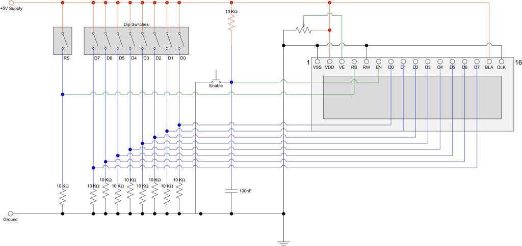
Interfacing with an HD44780 compatible display using DIP switches and a few other components. The module utilized is a 16 character x 2 line display that is in stock. It employs an ST7065C controller, which is compatible with the...
A newcomer is seeking a welcoming environment and expresses a desire to share a considerable amount of information. In the context of electronic schematics, it is essential to facilitate an inclusive environment for individuals at all levels of expertise. This...
The following circuit illustrates a Bass-Treble Tone Control Circuit electronic diagram based on the LM1035N integrated circuit (IC). Features include a 0.3 Vrms input level, 80 dB signal noise ratio, 75 dB volume control, ±15 dB typical tone control,...
These are small lights with a stake on the bottom that can be inserted into the ground along driveways or sidewalks, featuring a solar panel on top. The solar cell charges a AA NiCd battery during the day, and...
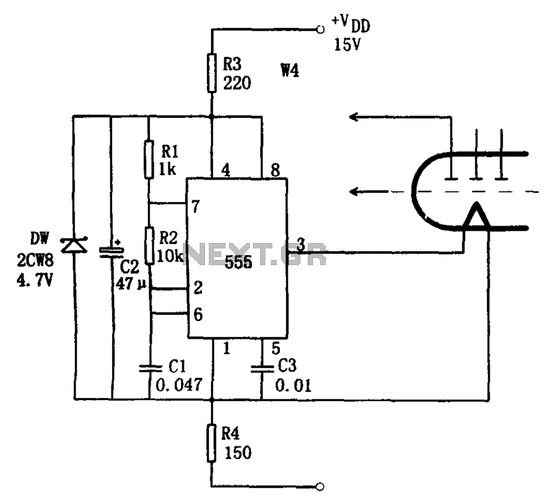
The economic fluorescent display circuit is illustrated in the figure. The primary component of this circuit is the 555 timer configured as a multivibrator. The oscillation frequency is determined by the components R1, R2, and C1, with a frequency...
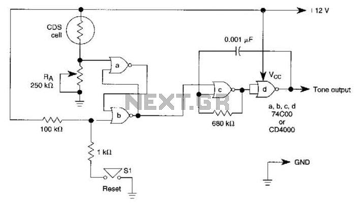
A decrease in the resistance of the CDS cell when light strikes it activates latch A and B, enabling tone oscillator C and D, which produces an output of about 1000 Hz. RA sets the trip level. SI resets...