
Solar Power walkway marker Led display
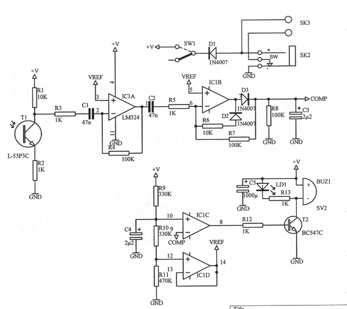
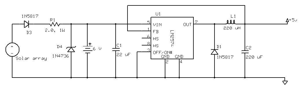
The described circuit operates as a solar-powered LED lighting system, primarily designed for outdoor use along pathways. The key components include a solar panel, a rechargeable battery, and a light-activated switching mechanism. The solar panel collects sunlight and converts it into electrical energy, which is stored in a rechargeable AA NiCd battery. The diode in the charging circuit ensures that the battery does not discharge back into the solar panel when there is insufficient light, thereby preserving the stored energy for nighttime use.
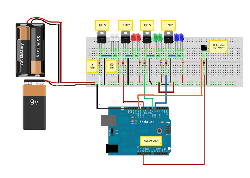
The integration of the CdS photoresistor is crucial for automatic operation. As ambient light levels change, the photoresistor alters its resistance, creating a voltage divider with the 10k and 1k resistors. This setup allows for the detection of light levels; when sufficient light is present, the photoresistor's low resistance activates the transistor Q1, which in turn controls the state of the circuit. The design ensures that the LED remains off during the day, conserving battery power for nighttime illumination.
In darkness, the high resistance of the CdS photoresistor turns off the right transistor, which releases the oscillation control, allowing the circuit to activate the LED. The use of surface-mounted components, including the transistors and the unmarked capacitor, indicates an effort to minimize the physical footprint of the circuit board while maintaining functionality and reliability. This compact design is well-suited for outdoor applications where space is limited and durability is essential. Overall, the circuit exemplifies an efficient approach to solar-powered lighting, combining renewable energy with automated control to enhance usability.These are the little lights with the stake on the bottom that you can push into the ground along your driveway or sidewalk and have the solar panel on top. The solar cell charges a AA NiCd battery during the day and at night the battery powers the LED. The circuit board in this particular model was originally designed to hold a pair of 5mm amber L EDs, but the manufacturer apparently found a source of higher power 10mm amber LEDs and the final product only needs one of these. Due to the limited space, many of the components are surface mount. The transistors are both 2N3904 equivalent surface mounts. Unfortunately, the capacitor is also surface mount and is unmarked. The charging circuit is fairly simple and has a photovoltaic solar cell to charge the battery and a diode to prevent the battery from powering the cell when it`s dark.
Now moving along, there is a cadmium sulphide (CdS) photo resistor, a 10k resistor and a 1k resistor that forms a voltage divider at the base of Q1. When light hits the photo resistor, it has a low resistance which is amplified by the transistor. The collector is tied to the base of the left hand transistor, so when it`s on it clamps its base to ground and prevents it from oscillating.
When it`s dark and the CdS Cell has a high resistance, the right transistor is off which allows the rest of the circuit to begin oscillating. 🔗 External reference
Related Circuits
Today, nearly all computers are equipped with logic blocks designed to implement a USB port. In practice, a USB port can deliver over 100 mA of continuous current at 5V to the peripherals connected to the bus. This capability...
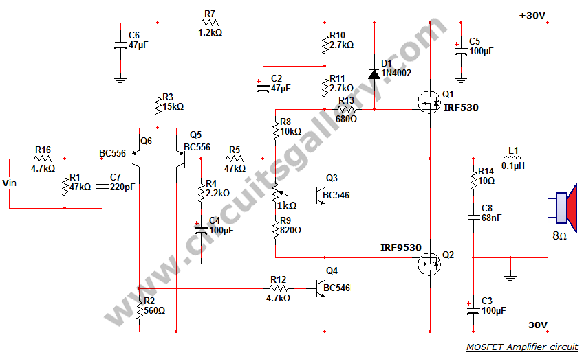
This is a MOSFET transistor-based power amplifier circuit that operates within a voltage range of +35V to -35V. The input voltage is pre-filtered and pre-amplified before being applied to the MOSFET switch. The pre-audio amplifier consists of a differential...
A 0.1µF capacitor and a 500µF electrolytic capacitor were connected to both the transmitter and the receiver, but the system did not function as expected. Attempts to add diodes were also unsuccessful. Clarification is needed regarding the behavior of...
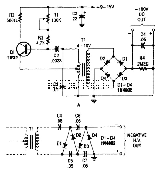
The combination of a Hartley oscillator and a step-up transformer can generate significant negative high voltage, particularly when the voltage output of the transformer is multiplied by the circuit in B. The Hartley oscillator is a type of LC oscillator...
The project involved the use of three solar cells wired in parallel, accompanied by a large 4700 µF capacitor on a perf board. A total of 13 such assemblies were created, resulting in 39 solar cells and 13 capacitors,...
A wooden table features numerous holes of varying diameters designed to accommodate optical fibers. Due to the size of the ceiling lamp (90 cm x 60 cm), it was not feasible to utilize a single bundle of fibers, resulting...