
Bass-treble Tone Control Circuit With LM1035N IC
The Bass-Treble Tone Control Circuit utilizing the LM1035N IC is designed to enhance audio signal processing by allowing users to adjust the bass and treble levels of the audio output. The IC provides a robust architecture that supports a variety of audio applications, ensuring high fidelity and minimal distortion.
The circuit operates with a specified input level of 0.3 Vrms, which is suitable for line-level audio signals. The signal-to-noise ratio of 80 dB indicates a high-quality audio output, minimizing unwanted noise during operation. The volume control feature, rated at 75 dB, allows for significant attenuation of the audio signal, providing flexibility in output levels.
Tone control is achieved through the use of variable resistors and capacitors, allowing users to modify the bass and treble frequencies by ±15 dB. This feature is critical for tailoring the audio output to suit personal preferences or specific acoustic environments. The circuit is designed to maintain a channel separation of 75 dB, ensuring that left and right audio channels remain distinct and clear, which is essential for stereo sound applications.
The power supply requirements for the circuit range from 9V to 16V, making it compatible with various power sources. The inclusion of passive components such as capacitors and resistors is vital for filtering and stabilizing the audio signals, while the switch allows for easy operation and control of the circuit.
Overall, this Bass-Treble Tone Control Circuit is a versatile and essential component in audio electronics, providing users with the ability to customize their listening experience effectively.The following circuit shows about Bass-treble Tone Control Circuit electronic circuit diagram. This circuit based on the LM1035N IC. Features: 0. 3 Vrms input level, 80 dB Signal noise, 75 dB volume control, ±15 dB typical Tone Control, 75 dB Channel separation, 9V to 16V supply voltage. Component: IC, Capacitor, Resistor, Switch. [f ree-circuits. com] Tags: Capacitor, circuit diagram, control circuit, control diagram, control schematic, electronic circuit, electronic control, IC, Resistor, schematic diagram, switch We aim to transmit more information by carrying articles. Please send us an E-mail to wanghuali@hqew. net within 15 days if we are involved in the problems of article content, copyright or other problems.
We will delete it soon. 🔗 External reference
Related Circuits
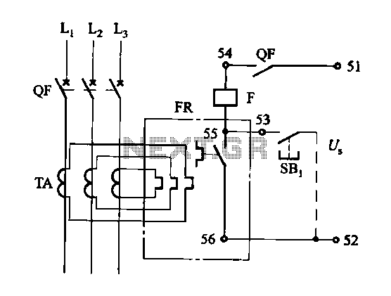
The DK-5A, 5D, and SDb control boxes are equipped with a thermal electromagnetic overcurrent release, as depicted in Figure 6-80. The trip mechanism provides both overload and instantaneous short circuit protection with a long delay feature. In the figure,...
With this counter you can count laps for example (in conjunction with the Simple light trap). The circuit uses two TTL ICs 74LSxx the series. The left IC is a decimaalteller. The input pulses 14 are counted and converted...
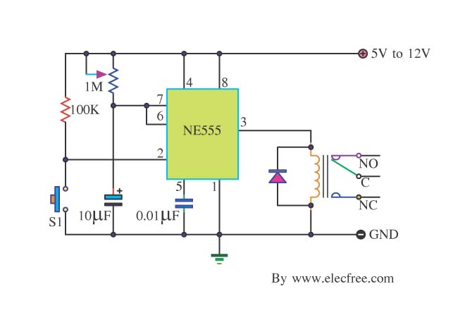
Many friends take an interest in the circuit involving the highly popular IC 555, which is an integrated circuit. This circuit sets the time in a basic manner. The IC 555 timer is a versatile and widely utilized component in...
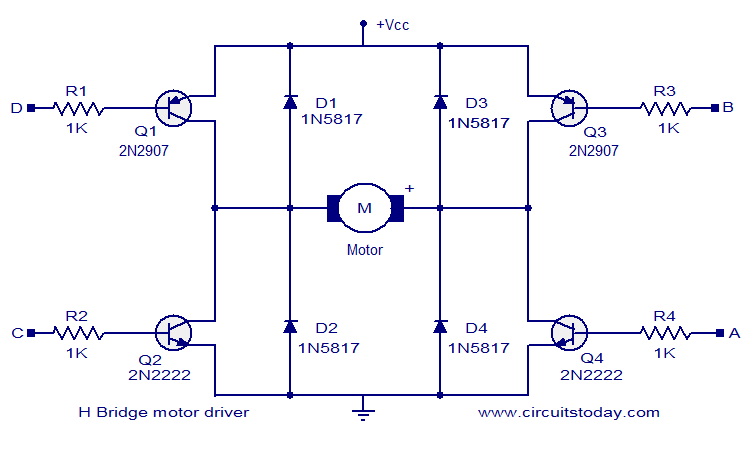
The circuit presented is a simple H-bridge motor driver circuit utilizing commonly available components. An H-bridge is an efficient method for driving motors and is widely used in various electronic projects, particularly in robotics. The circuit illustrated is a...
The high input impedance, high slew rate, and high voltage characteristics of the CA3140 operational amplifier make it suitable for use in a Wien-bridge sine wave oscillator. The basic circuit configuration for the Wien-bridge sine wave oscillator is depicted...
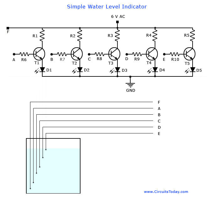
A simple water level indicator project with a circuit diagram for home and industry. This water tank level sensor can be utilized for any liquid level indicator projects. The water level indicator circuit is designed to monitor and display the...
Warning: include(partials/cookie-banner.php): Failed to open stream: Permission denied in /var/www/html/nextgr/view-circuit.php on line 713
Warning: include(): Failed opening 'partials/cookie-banner.php' for inclusion (include_path='.:/usr/share/php') in /var/www/html/nextgr/view-circuit.php on line 713