
automatic headlight reminder
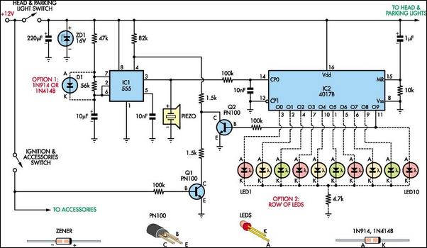
The headlights reminder circuit is designed to prevent the common issue of draining the battery by leaving the car lights on, particularly in older vehicles lacking an automatic warning system. The core of this circuit consists of two integrated circuits: a 555 timer (IC1) and a 4017B decade counter (IC2).
IC1 operates in astable mode, generating a continuous square wave output that serves as a clock signal for IC2. The 4017B decade counter counts the clock pulses from IC1 and activates a series of output pins corresponding to the sequence of the LEDs. Each LED lights up in succession, creating a visual indication that the headlights are on. The design incorporates a reset mechanism for IC1, which is triggered by transistor Q2 after a delay of approximately 10 seconds, effectively stopping the oscillation of the 555 timer and silencing the piezo siren.
The circuit is designed to integrate seamlessly with the vehicle's ignition system. When the ignition is on, Q1 remains activated, keeping pin 4 of IC1 low and preventing any clock pulses from reaching IC2. This ensures that the reminder system is inactive while the vehicle is in use. Once the ignition is turned off, Q1 deactivates, allowing IC1 to begin oscillating, which in turn triggers the piezo siren and starts the LED sequence.
The output from IC2 is configured such that once the last LED (LED10) has illuminated, it remains lit until the system is reset. This is achieved through the high output from pin 11 (O9) of IC2, which activates Q2, thereby pulling pin 4 of IC1 low and halting the oscillator. The use of multiple colored LEDs enhances the visibility and aesthetic appeal of the circuit, although uniformity in color can be achieved if preferred.
For flexibility, the circuit allows for the inclusion of an optional diode (D1) that can modify the frequency of IC1, thus changing the rate at which the LEDs illuminate. This customization can be beneficial depending on user preference or specific vehicle requirements. Additionally, the design allows for the alarm to automatically retrigger if the headlights are turned off and then back on again, ensuring continued protection against battery drain. LED1 serves as a constant indicator when the headlights are active, providing a straightforward visual cue to the driver. If desired, the LED display can be omitted entirely by not installing the LEDs, simplifying the circuit's implementation.Do you drive an older car without an automatic "lights-on" warning circuit If so, you`ve probably accidentally left the lights on and flattened the battery on one or more occasions. This headlights reminder circuit will prevent that. It`s more complicated than other circuits but it`s also more versatile. As shown, the circuit uses two low-cost IC s. IC1 is a 555 timer which is wired to operate in astable mode. Its output clocks IC2, a 4017B decade counter. IC2 in turn drives a row of indicator LEDs and also resets IC1 (after about 10s) via transistor Q2. when the ignition is on, transistor Q1 is also on and this pulls pin 4 of IC1 low. As a result, IC1 is held reset and no clock pulses are fed to IC2. Conversely, if the ignition is turned off, Q1 will turn off and so IC1 will start oscillating and sound the piezo siren. At the same time, IC1 will clock IC2 and so LEDs 1-10 will light in sequence and stop (after about 10s) with the last LED (LED10) remaining on.
That`s because, when IC2`s O9 output (ie, pin 11) goes high, Q2 also turns on and this pulls pin 4 of IC1 low, thus stopping the oscillator (and the siren). That different colored LEDs are used to make the display look eye-catching but you make all LEDs the same color if you wish.
Installing optional diode D1 will alter IC1`s frequency and this will alter the display rate. Finally, if the lights are turned off and then back on again, the alarm will automatically retrigger. LED1 is always on if the lights are turned on. If you don`t want the LED display, just leave the LEDs out. 🔗 External reference
Related Circuits
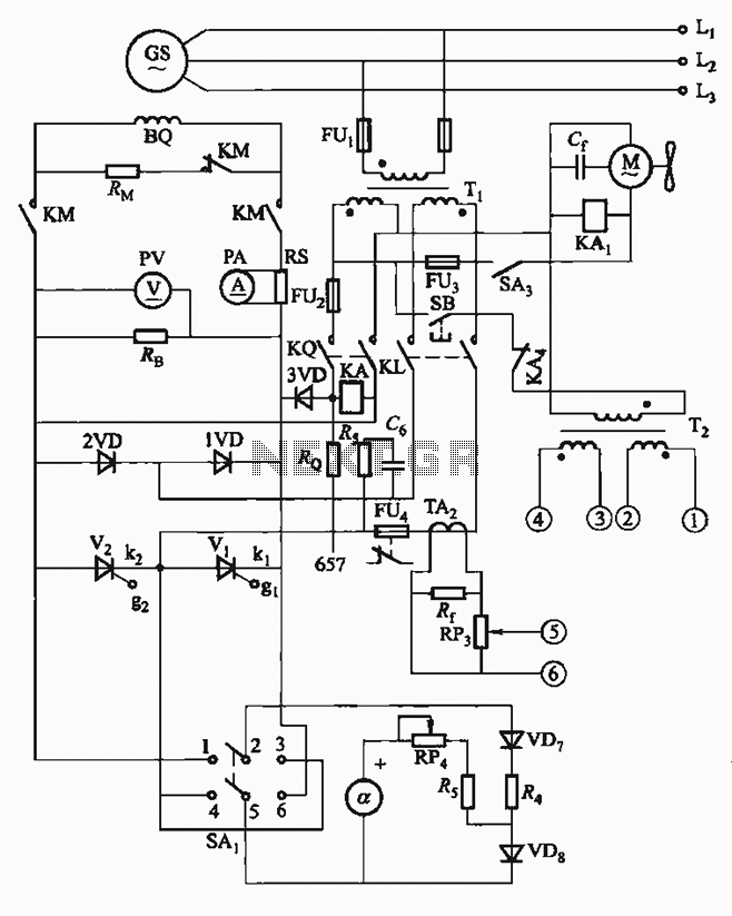
The FKL-32 type automatic thyristor excitation device is designed for synchronous generators with a terminal voltage of 400V and a capacity of 500kW or below. It is used for the automatic adjustment of excitation. The FKL-32 automatic thyristor excitation device...
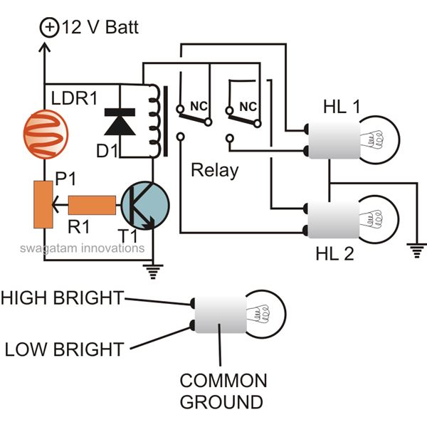
The circuit described here can be built and used in a vehicle for an automatic dipping and dimming operation of the headlamps in response to intense lights coming from opposite vehicle headlamps. This situation is often encountered while driving...
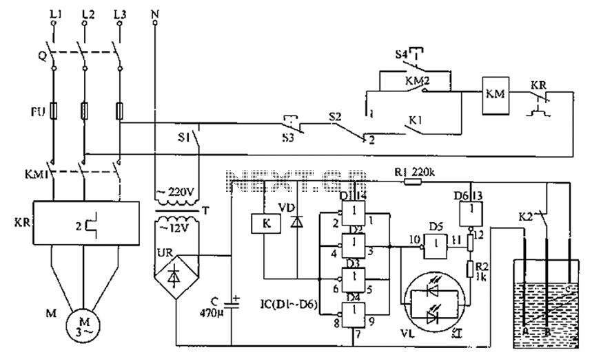
The liquid level automatic controller circuit consists of a power circuit, a control instruction level detection circuit, and a starter control circuit. The power circuit is formed by a power transformer, a rectifier bridge, and a filter capacitor. The...
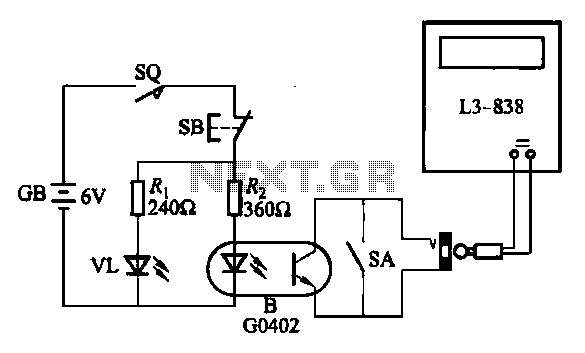
An electronic calculator features an automatic counting interface circuit, as illustrated in the accompanying figures. Figure (a) depicts a stroke switch controlled via optocoupler B. Figure (b) shows the application of a reed switch (KR) for pulse control signals....
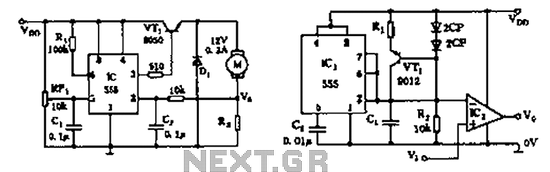
The circuit consists of a 555 motor automatic governor configuration. It includes flip-flops, a 555 timer, and a switching tube. A sampling circuit is formed by connecting R7 and the motor in series. RP1 is used to control the...
The circuit consists of inverter and charger sections. The inverter section utilizes the NE555 timer, while the charger section is based on the LM317 adjustable regulator. In the inverter section, the NE555 is configured as an astable multivibrator, generating...