
touch sensor switch using inverters
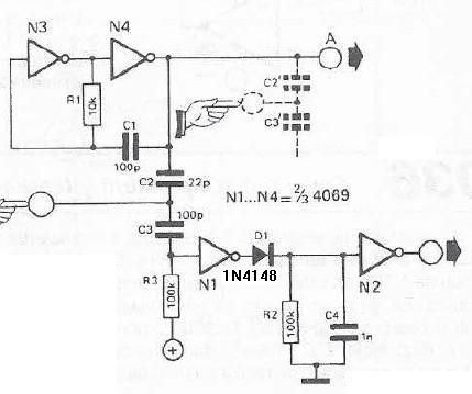
The touch sensor switch circuit utilizes inverters N1 and N2 to create a responsive control mechanism. The oscillator comprised of N3 and N4 generates a continuous 1 MHz signal, which is crucial for the operation of the touch sensor. When a user touches the sensor, the inherent capacitance of the human body effectively alters the input conditions at N1, leading to a reduction in the voltage level at its input. This change is detected by N1, which then influences the output state of N2.
The circuit's design ensures that in the absence of a touch, N1 maintains a high voltage at its input, resulting in a logical '1' output from N2. This condition signifies that the system is in standby mode. Upon touching the sensor, the voltage drop at the input of N1 causes N2 to switch to a logical '0', indicating that the touch has been registered.
After the touch event, the circuit includes a capacitor (C4) that temporarily stores charge. The diode (D1) allows for the controlled discharge of this charge, which contributes to the timing of the output signal. As the charge dissipates, N2 returns to a logical '1', effectively resetting the system after a brief period. This feature ensures that the touch sensor remains responsive while also providing a clear indication of touch events through the logical state changes at the output.
Overall, this touch sensor switch circuit exemplifies a simple yet effective design that leverages basic electronic components to achieve reliable touch detection and control functionality.This touch sensor switch can is designed using inverters (N1, N2)and some common electronic components. In standby state at the entrances of N1 there is a signal produced by oscillator N3/N4. At the touch sensor hand capacity forms a bridge to the ground for the 1MHz signal so that the voltage signal at the entrance of N1 decreases more (at the ex
it of N2 is logical 1). After the release of contact, a signal charge C4 through D1 Mhz, so the output of N2 is 0 logic after short time. 🔗 External reference
Related Circuits
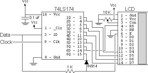
Alphanumeric LCD displays are widely used in microcontroller applications due to their versatility and ability to enhance project functionality. They provide text messages that offer user instructions and feedback, contributing to a more professional and user-friendly experience. LCDs are...
A reader named Andrea ([email protected]) submitted a circuit designed for educational purposes. The primary objective is to demonstrate how to electronically toggle an output state using only a push-button switch. According to Andrea, this simple circuit can drive a...
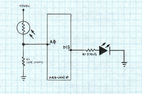
A project is underway to determine the number of sun hours available at a specific location and to track this data over time as part of solar power installation design. The concept involves utilizing a light detector exposed to...
The documents, software, tools, and links are provided to enhance the capabilities of electronics students, hobbyists, or professionals by sharing information. This information and the associated links should be utilized by website visitors at their own risk and responsibility....
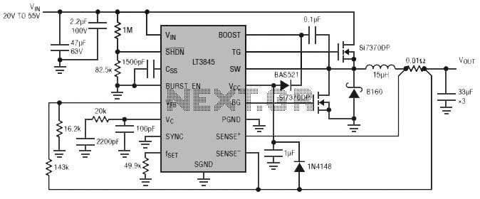
Burst Mode operation maintains high efficiency at light loads by reducing IC quiescent current to 120 µA. Light load efficiency is also improved with the reverse inductor current inhibit function, which supports discontinuous operation. Additional features include an adjustable...
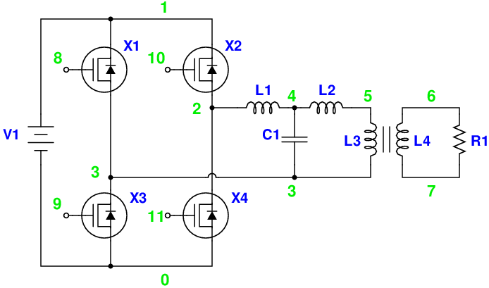
Magic Sinewave Analysis using SPICE and a Simple Inverter Circuit. This document discusses the analysis of a sinewave signal generated by a simple inverter circuit using SPICE simulation software. The inverter circuit is designed to convert a DC input voltage...
Warning: include(partials/cookie-banner.php): Failed to open stream: Permission denied in /var/www/html/nextgr/view-circuit.php on line 713
Warning: include(): Failed opening 'partials/cookie-banner.php' for inclusion (include_path='.:/usr/share/php') in /var/www/html/nextgr/view-circuit.php on line 713