
Alternating Relay Switch
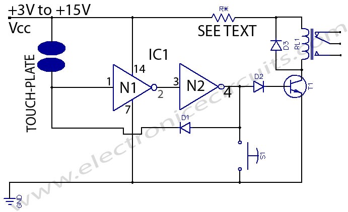
The described circuit utilizes a monostable relay configuration, which is essential for applications requiring a temporary output state. The circuit operates with a single push-button switch that serves as the user interface for toggling the relay's state. When the button is engaged, the integrated circuit (IC) produces a high output signal at pin 3, which is typically connected to the base of the Q1 transistor. The Q1 transistor's role is to control the relay's operation indirectly by managing the power supply to the relay coil.
In this scenario, pressing the button results in the Q1 transistor turning off, which may seem counterintuitive; however, this behavior is characteristic of a monostable circuit where the output state is held temporarily. Upon releasing the button, the relay coil is energized, which closes the switch between terminals 5 and 9, allowing current to flow through the connected load.
The second part of the operation occurs when the button is pressed again. This action causes the IC output to return to a low state, which turns on the Q3 transistor. The Q3 transistor is likely configured to control another aspect of the circuit or to reset the relay back to its initial state, thereby allowing for repeated toggling of the relay's output.
This circuit exemplifies an efficient method of controlling a relay using minimal components, making it suitable for educational demonstrations on electronic switching mechanisms. The design can be further enhanced by incorporating additional features such as debounce circuitry for the push-button switch, which would improve reliability and prevent unintended multiple activations due to mechanical bounce. Overall, this circuit serves as a fundamental example of relay control using basic electronic components.Our reader Andrea (andrea[dot]perugia[-at-]gmail[dot] com) sent his circuit to us, and he creates the circuit for educational intent. The main purpose is to show that you can toggle an output state electronically, although physically you use only a push button switch.
Here is what he said about the cicuit : This simple circuit can be utilized to d rive a monostable relay, using a single button switch. When I press the button IC output (pin 3) assumes the high level, but Q1 transistor switches off. So when I release the button the relay is energized (now the exchange switch is closed on 5 and 9). When I press the button again IC output assumes the low level, but Q3 transistor switches on: We aim to transmit more information by carrying articles. Please send us an E-mail to wanghuali@hqew. net within 15 days if we are involved in the problems of article content, copyright or other problems.
We will delete it soon. 🔗 External reference
Related Circuits
This is a remote on-off switch circuit. This circuit allows the use of a small switch to control larger AC currents from high-power devices. The remote on-off switch circuit operates by utilizing a low-power control signal to manage a high-power...
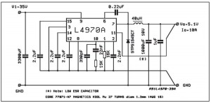
A small-sized and easy-to-build 5V 10A power supply circuit is being sought. This circuit utilizes the L4970A integrated circuit as a 10A switching regulator. It is essential that the power supply input can handle a current of 10A to...
This is a touch switch designed to control LEDs, relays, and similar devices through a buffer transistor stage. It can be constructed using any CMOS inverter chip. The touch switch circuit operates by utilizing the capacitive touch sensing principle, which...
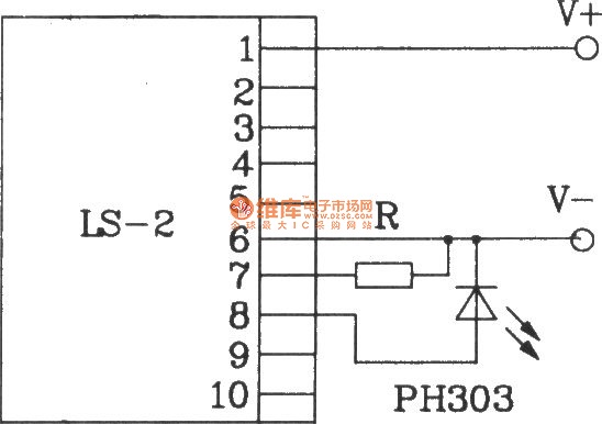
The LS-2 remote control switch infrared sensor module is similar to the LS-18 but functions as a reflector. The LS-2 pin diagram and internal block diagram provide insights into its electrical parameters. The operating voltage for the LS-2 remote...
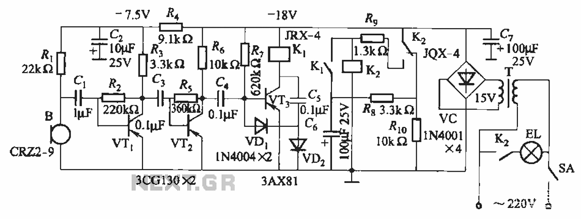
The circuit utilizes relay control. The voice switch operates as follows: upon the first clap, the load (lights) is activated; upon the second clap, the load (lights) is deactivated. This system can be employed to control lighting in residential...
This circuit requires a control current that is 100 times smaller than that required by standard optically isolated solid-state relays. It is particularly suitable for battery-powered systems. By utilizing a combination of a high-current TRIAC and a very sensitive...