
Magic Sinewave Analysis using SPICE and a Simple Inverter Circuit
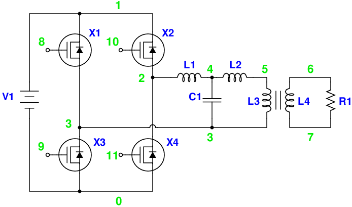
This document discusses the analysis of a sinewave signal generated by a simple inverter circuit using SPICE simulation software. The inverter circuit is designed to convert a DC input voltage into an AC output voltage, producing a sinewave signal that can be utilized in various applications.
The circuit typically includes essential components such as a DC power supply, an inverter (which may consist of transistors or operational amplifiers), and passive components like resistors and capacitors. The inverter's operation is based on switching principles, where the DC input is periodically inverted to create an alternating current (AC) output.
In the SPICE simulation, the circuit is modeled to observe the output waveform characteristics, including amplitude, frequency, and distortion. The simulation allows for the adjustment of component values to optimize performance and analyze the effects of different configurations on the sinewave output. By examining the results, engineers can gain insights into the circuit's behavior and make informed decisions regarding design improvements.
The analysis may also include frequency response testing, where the inverter's output is evaluated across various frequencies to determine its efficiency and stability. Additionally, the simulation can highlight potential issues such as clipping or phase distortion that may arise during operation.
Overall, this analysis serves as a valuable tool for understanding the behavior of inverter circuits and the generation of sinewave signals, facilitating advancements in electronic design and applications.Magic Sinewave Analysis using SPICE and a Simple Inverter Circuit. 🔗 External reference
Related Circuits
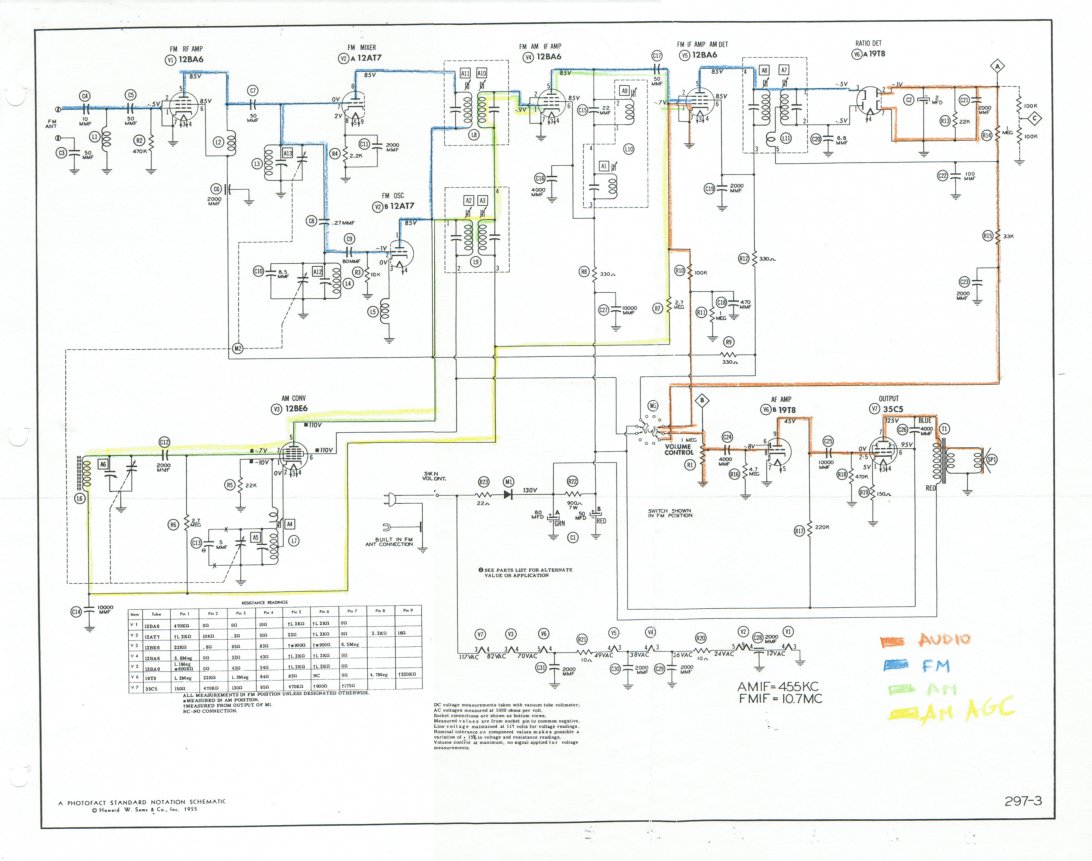
This document outlines the restoration of an antique AM/FM Granco 720 radio. It explores the design of the AM and FM receivers, detailing the alignment of these receivers, discussing repairs, and evaluating the radio's performance. The restoration of antique...
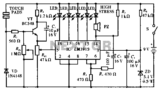
The circuit operates by utilizing two self-test table contact pads that detect electric pressure changes across the skin. The input voltage is 5 volts, which can drive up to 10 LEDs (the current configuration includes only 5 LEDs). When...
Note: Do not build or use this if you do not have any knowledge in electrical or electronics. This project is not safe for beginners, and the voltage involved is dangerous and can cause electrocution. Do not exceed the...
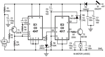
The following circuit illustrates an Infrared Toy Car Motor Controller Circuit Diagram. This circuit is based on the 4017 IC. Features: operating at .. The Infrared Toy Car Motor Controller Circuit utilizes a 4017 Decade Counter IC, which is integral...
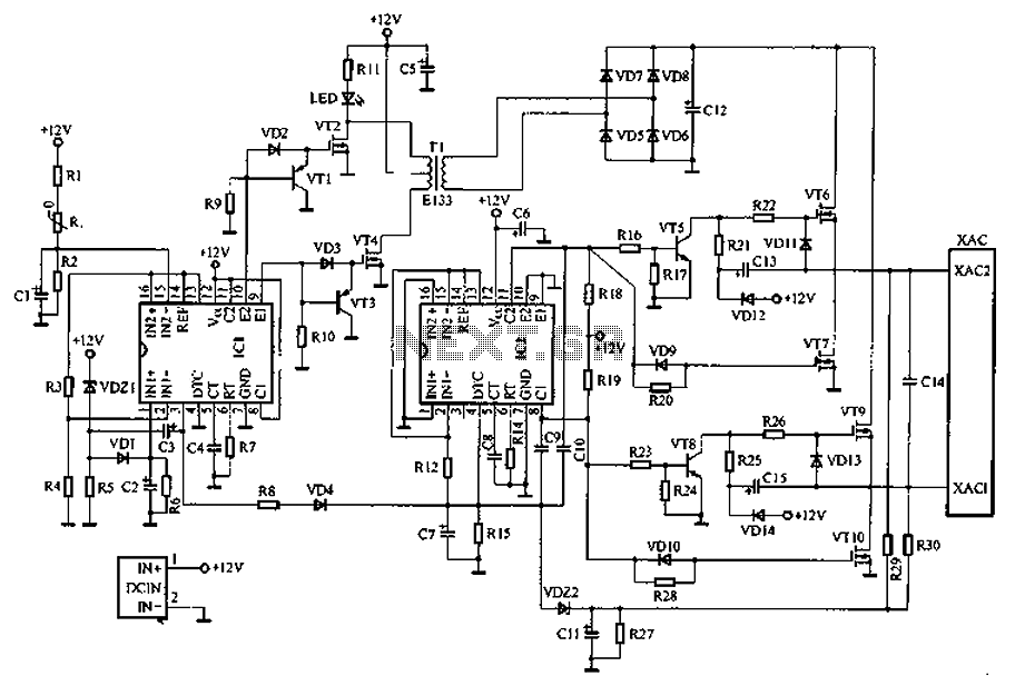
Car inverter specifications include an input voltage range of DC 10V to 14.5V, output voltage of AC 200V to 220V with a tolerance of 10%, output frequency of 50Hz with a tolerance of 5%, and an output power range...
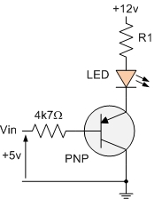
The PNP transistor is the exact opposite of the NPN transistor discussed in the previous tutorial. In this type of transistor construction, the two diodes are reversed compared to the NPN type, resulting in a Positive-Negative-Positive configuration, with the...