
Touch switching 12V Light

The described circuit employs two distinct configurations utilizing bipolar transistors and a power MOSFET to achieve touch-sensitive activation of a lamp. In the first configuration, three bipolar junction transistors (BJTs) are arranged in a cascading manner to amplify the small current generated by the human body's touch, which is typically in the microamp range. The touch contact is connected to the base of the first transistor, with the emitter connected to ground. The collector of the last transistor in the series can handle higher currents, allowing it to drive a load such as a lamp rated at 20 watts. The necessity of three transistors arises from the fact that each BJT has a limited current gain, usually below 200, thus multiple stages are required to achieve the necessary current amplification.
In the second configuration, a power MOSFET is utilized. The gate of the MOSFET is activated by a voltage of approximately 6 volts, which is achieved when the resistance across the touch contacts (around 2 Megohms) matches a fixed resistance connected between the gate and source. This configuration allows the MOSFET to remain in an off state until the touch contact is engaged, at which point the gate capacitance charges to the threshold voltage, turning the MOSFET on without drawing any current from the gate. This characteristic of the MOSFET is advantageous as it minimizes power loss during operation.
Both circuits are designed to be responsive to the relatively high skin resistance of 2 Megohms or less, ensuring functionality under typical conditions. For applications requiring higher current capabilities, the output load (a lamp in this case) can be substituted with a 12-volt relay, with a diode placed in parallel across the relay coil to protect against back EMF when the relay is deactivated. This design enhances the versatility and reliability of the circuit in various electronic applications.The circuit on the right uses three bipolar transistors to accomplish the same result with the touch contact referenced to the negative or ground end of the supply. Since the base of a bipolar transistor draws current and the current gain is usually less than 200, three transistors are needed to raise the microamp current level through the touch contacts to a couple amps needed by the light.
For additional current, the lamp could be replaced with a 12 volt relay and diode across the coil. The circuits below light a 20 watt lamp when the contacts are touched and the skin resistance is about 2 Megs or less. The circuit on the left uses a power MOSFET which turns on when the voltage between the source and gate is around 6 volts.
The gate of the MOSFET draws no current so the voltage on the gate will be half the supply voltage or 6 volts when the resistance across the touch contacts is equal to the fixed resistance (2 Megs) between the source and gate. 🔗 External reference
Related Circuits

A simple 5-volt switching power supply electronic circuit project can be designed using the FAN302HL, a highly integrated PWM controller integrated circuit. This IC provides several features that enhance the performance of general flyback converters. The constant-current control of...
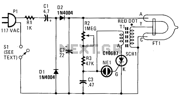
In this strobe light, two circuits are required: one circuit charges a capacitor to create a 320 V DC potential between the cathode and anode of the flashtube, while the other circuit generates bursts of approximately 4000 V to...

Approximately one month ago, an attempt was made to reverse engineer a low-cost LED color-changing light bulb. With assistance, the circuit has been mapped out, and control over the bulb has been established. However, several aspects of this device...
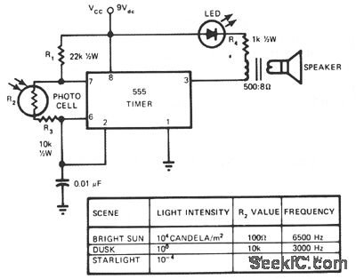
This circuit's frequency of oscillation increases directly with light intensity. The greater the light intensity, the higher the frequency of the oscillator. The 555 timer operates in astable oscillator mode, where frequency and duty cycle are controlled by two...
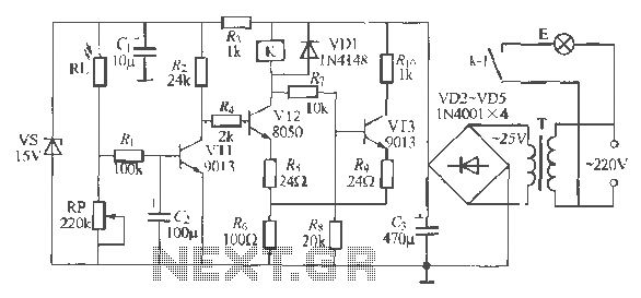
The circuit operates as a light-activated switch that controls white moving lights. It features high sensitivity, stable performance, and good anti-interference characteristics. A photosensitive resistor (RI) is employed to detect ambient light levels. During the day, the resistor exhibits...

One of the motors consistently exhibits hesitation and operates in an unpredictable manner. When tested independently, the motors function correctly without any hesitation. The GPS unit features a Low Voltage TTL serial output on its connector, but a reliable...
Warning: include(partials/cookie-banner.php): Failed to open stream: Permission denied in /var/www/html/nextgr/view-circuit.php on line 713
Warning: include(): Failed opening 'partials/cookie-banner.php' for inclusion (include_path='.:/usr/share/php') in /var/www/html/nextgr/view-circuit.php on line 713