
Traffic Light Controller

The four-way traffic light controller is an essential electronic system designed to manage traffic flow at intersections by controlling the operation of Red, Yellow, and Green LEDs. The core of this system is the AT89C2051 microcontroller, which is an 8-bit microcontroller from the 8051 family, known for its simplicity and effectiveness in handling control tasks.
The traffic light system operates in a cyclic manner, where each color LED is illuminated for a specific duration to ensure safe passage for vehicles and pedestrians. The Red LED signifies that vehicles must stop, the Green LED indicates that vehicles may proceed, and the Yellow LED serves as a warning that the light is about to change.
The circuit typically consists of the following components:
1. **Microcontroller (AT89C2051)**: This component is programmed to control the timing and sequence of the LED operation. It has a built-in oscillator and several I/O pins that can be configured to drive the LEDs.
2. **LEDs**: Three types of LEDs (Red, Yellow, Green) are used to indicate the traffic signals. Each LED is connected to a specific output pin of the microcontroller, allowing for individual control.
3. **Resistors**: Current-limiting resistors are used in series with each LED to prevent excessive current flow, which could damage the LEDs. The resistor values are selected based on the forward voltage and current ratings of the LEDs.
4. **Power Supply**: The microcontroller and LEDs require a stable power supply, typically 5V. This can be achieved using a voltage regulator if a higher voltage source is used.
5. **Timing Circuit**: The timing for each traffic light phase can be implemented using software timers within the microcontroller. The durations for Red, Yellow, and Green lights can be adjusted based on the specific traffic conditions or requirements.
6. **Optional Components**: Additional components such as push buttons for pedestrian crossing signals or sensors for vehicle detection can be integrated into the system to enhance functionality.
The programming of the AT89C2051 involves writing a code that defines the sequence of operations for the LEDs, including the timing for each light change. This code is typically written in assembly or C language and uploaded to the microcontroller via a suitable programmer.
In summary, the four-way traffic light controller utilizing the AT89C2051 microcontroller provides a reliable and efficient method for managing traffic at intersections, ensuring safety and order in vehicular movement. The design can be further enhanced with additional features based on specific traffic management needs.Four way Traffic light controller which Has Red, Yellow and Green LEDS. It uses the AT89C2051. 🔗 External reference
Related Circuits

A prerequisite for this article is that the GCC AVR programming environment is installed as described in the article "Programming the AVR microcontroller with GCC, libc 1.0.4." To avoid installation issues, using the AVR programming CD is recommended. When...
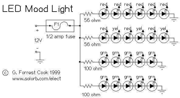
Power this project from sunlight with a CirKits solar power circuit board kit. Other LED lamp circuits can be seen at FC's Solar Circuits, another interesting LED project is my 13 Color LED Rainbow. This circuit makes a nice...
To troubleshoot the headlight system, switch the headlight switch ON and OFF and check if the headlight relay can be felt and heard clicking. This is indicated in the first schematic on the left side of the diagram. The...
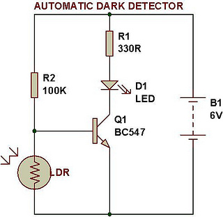
An automatic dark detector senses darkness. As the light level decreases and the light-dependent resistor (LDR) reaches the maximum threshold resistance, the circuit automatically activates the LED D1. Conversely, a light detector senses light, and when the light level...
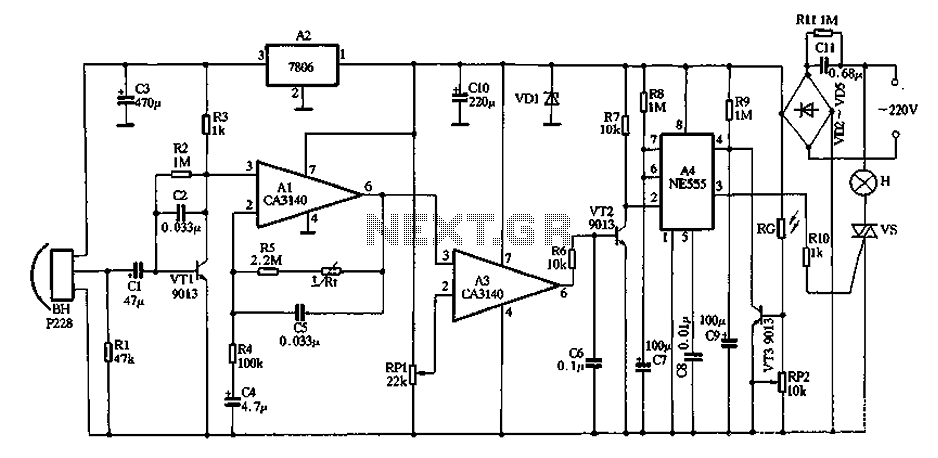
The core device is a circuit pyroelectric infrared sensor (BH). When it detects infrared radiation from a body, the sensor element responds to changes in temperature. As a thermoelectric element, its self-ferroelectric polarization value changes, causing a discharge of...
The 555 circuit described is a flashing bicycle light powered by four C, D, or AA cells (6 volts). It features two sets of 20 LEDs that flash alternately at approximately 4.7 cycles per second, utilizing the specified RC...