
40 LED Bicycle Light Using 555
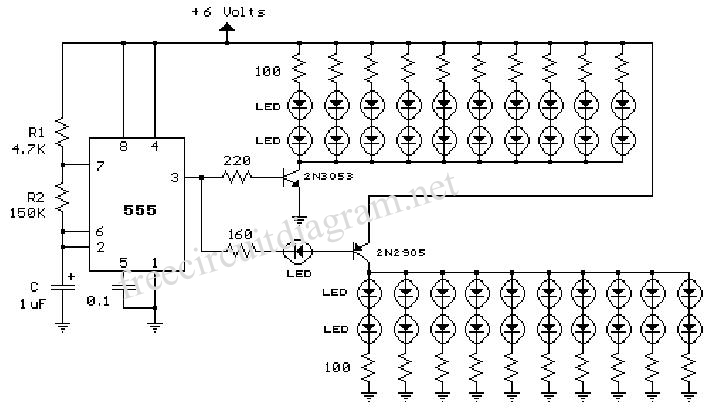
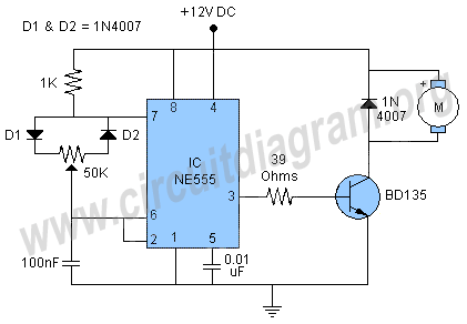
The described circuit employs a 555 timer configured in astable mode to create a pulsing signal that drives the LEDs. The RC values are crucial for determining the frequency of the flashing LEDs. The resistor R1 (4.7K) and R2 (150K) along with the capacitor (1uF) set the timing intervals for the output signal. The frequency of oscillation can be calculated using the formula:
\[ f = \frac{1.44}{(R1 + 2R2) \times C} \]
Substituting the given values into this formula yields a frequency of approximately 4.7 Hz, which corresponds to the alternating flashing of the LEDs.
The two transistors serve as amplifiers to drive the LED arrays, allowing them to draw more current than the 555 timer can provide alone. This is essential for achieving adequate brightness in the LEDs. The configuration of the transistors should be such that they are connected in a common emitter configuration, allowing for a greater output current while maintaining the switching characteristics dictated by the 555 timer.
The arrangement of the LEDs is such that they are grouped into two sets of 20, with each set connected to the collector of its respective transistor. The series connection of a single LED with the circuit may serve as a current-limiting device, ensuring that the current through the LED remains within safe operating limits.
Overall, this circuit design provides an effective solution for creating a visible and energy-efficient bicycle light, enhancing safety for cyclists during low-light conditions. The use of standard components, such as the 555 timer and common transistors, makes this circuit accessible for hobbyists and engineers alike.The 555 circuit below is a flashing bicycle light powered with four C,D or AA cells (6 volts). Two sets of 20 LEDs will alternately flash at approximately 4.7 cycles per second using RC values shown (4.7K for R1, 150K for R2 and a 1uF capacitor). Time intervals for the two lamps are about 107 milliseconds (T1, upper LEDs) and 104 milliseconds (T2 lower LEDs).
Two transistors are used to provide additional current beyond the 200 mA limit of the 555 timer. A single LED is placed in series with the. 🔗 External reference
Related Circuits
A very simple metal detector electronic project can be designed using a simple 555 timer integrated circuit. As you can see in the schematic circuit, this electronic project requires few external electronic parts. This circuit detects metal and also...
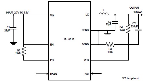
The ISL8012 is a high-efficiency, monolithic, synchronous step-down DC-DC converter that can be designed into a simple electronic project. It supports a maximum continuous output current of up to 2A from an input supply range of 2.7V to 5.5V....
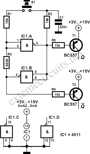
Using just two NAND or inverter gates, it is possible to build a D-type (or toggle) flip-flop with a push-button input. At power-up, the output of gate N2 is at a logical 1, ensuring that transistor T2 is switched...
Transmitting voice wirelessly using laser technology, along with tips and tweaks to enhance your computer operating system experience. The concept of transmitting voice wirelessly using laser involves utilizing modulated laser beams to carry audio signals over distances without the need...
This simple DC motor control or PWM circuit using a 555 IC can be utilized to regulate the speed of a DC motor. The circuit is straightforward and can be assembled quickly if all components are readily available. The described...
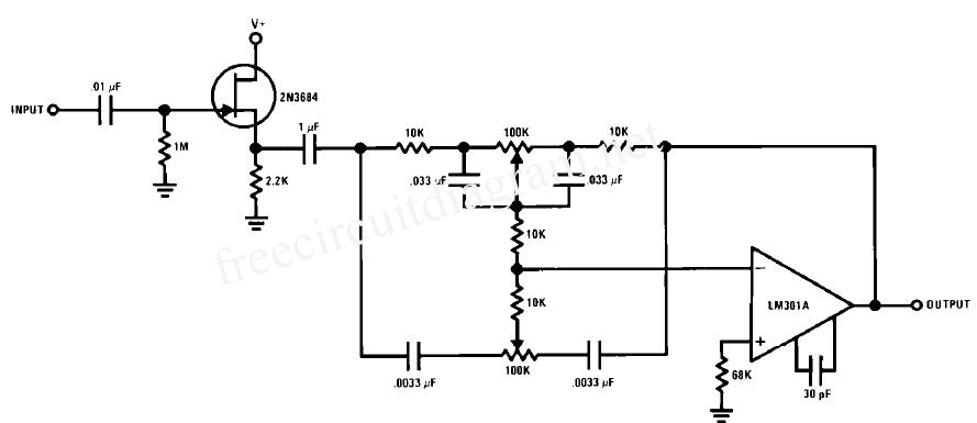
This circuit is a simple series tone control circuit utilizing the OP-Amp LM301A. The JFET 2N3684 provides high input impedance and low noise characteristics for the feedback buffer in the op-amp-based tone control. The tone control circuit described employs an...
Warning: include(partials/cookie-banner.php): Failed to open stream: Permission denied in /var/www/html/nextgr/view-circuit.php on line 713
Warning: include(): Failed opening 'partials/cookie-banner.php' for inclusion (include_path='.:/usr/share/php') in /var/www/html/nextgr/view-circuit.php on line 713