
Traffic Lights-LEDS
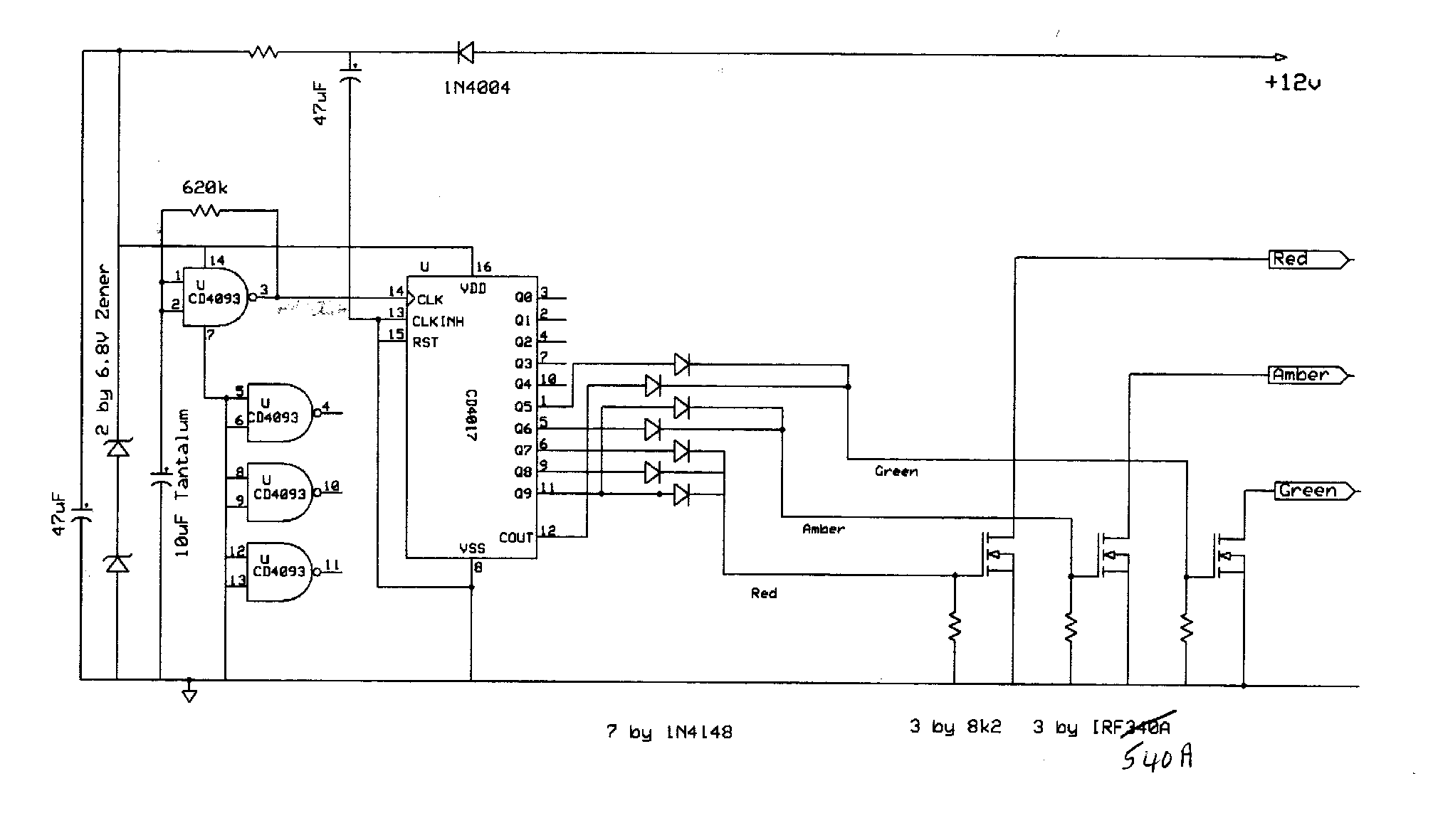
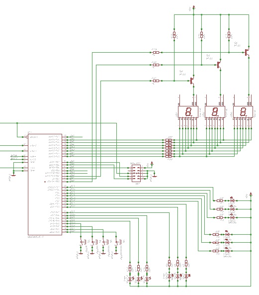
The circuit utilizes a 555 timer configured in astable mode, which generates a continuous square wave output. This output serves as the clock signal for the CD4017 decade counter IC. The frequency of the clock pulses can be adjusted by varying the values of the timing resistor and capacitor connected to the 555 timer. In this specific design, a 10K ohm resistor is employed to limit the current and set the timing interval.
The CD4017 IC features ten output pins, each corresponding to a specific count in the sequence. The outputs are activated sequentially with each clock pulse received from the 555 timer. The first five outputs correspond to the red LED, which remains illuminated for a total of five clock cycles. The outputs are connected to the respective traffic light LEDs: red, yellow, and green.
To ensure that the green and yellow LEDs can be illuminated for more than one count without causing a short circuit, diodes are employed. These diodes isolate the outputs of the CD4017, preventing backflow of current between the outputs when multiple LEDs are activated simultaneously. This configuration allows for a smooth transition between the traffic light states without interference.
Additionally, a capacitor and resistor are connected to pin 15 of the CD4017, which is used for the reset functionality. Upon powering the circuit, this reset mechanism ensures that the counter initializes to zero, thus turning on the red LED immediately. This design effectively creates a simple yet reliable traffic light control system, ensuring proper sequencing and timing of the light signals for safe traffic management.The 555 timer IC is connected for Astable Operation, the clock pulses are fed to the 4017 IC via the 10K resistor. The 4017 is a 10 stage counter, therefore the sequence of the traffic lights is spread over 10 clock pulses, 4on red, 1 on red & amber, 4 on green and 1 on amber.
We need red on for 5 pulses, so we connect the red LED to pin 12 which is on for the first 5 stages of the counter. The green and yellow LEDs are connected to the nescessary counter outputs, as both LEDs need to be on for more than one count, we use diodes to avoid a short circuit situation between outputs.
The capacitor and resistor on pin 15 of the 4017 are used to reset the counter to zero (red LED on) at initial power up. 🔗 External reference
Related Circuits
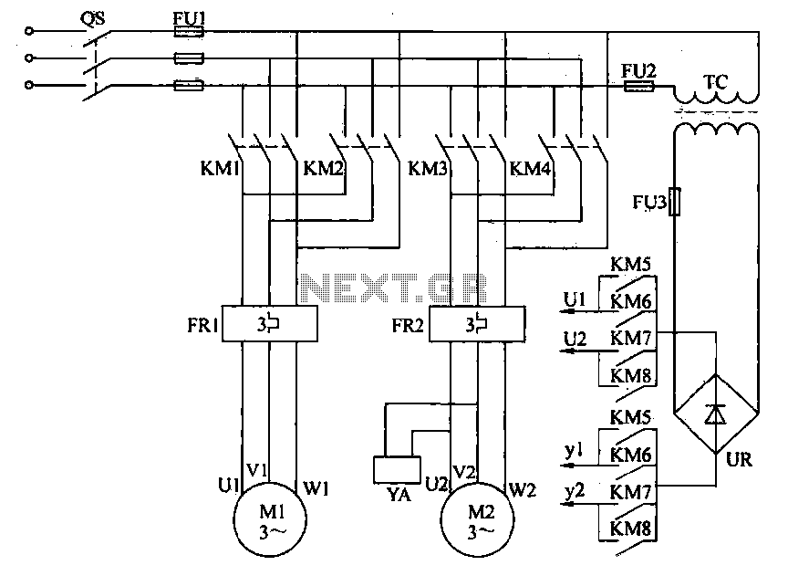
Electric driving is essential for modernizing plant material transport. Traditional control methods are primarily semi-manually operated automatic systems. To enhance efficiency, promote production automation, and reduce labor intensity, electrical automation for material transport is often implemented. This automation allows...
A board is to be designed with a single input of 120 volts and 600 watts, which will provide more than three outputs, each rated at 120 volts and 200 watts. These outputs will be designated as A, B,...
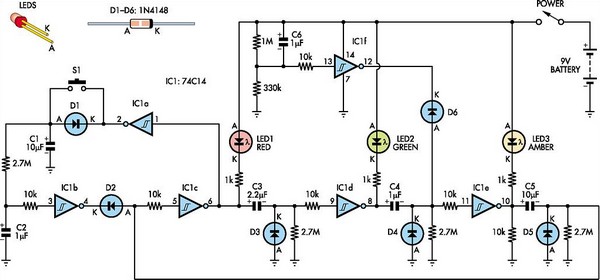
This toy traffic signal utilizes a single low-cost hex Schmitt-trigger inverter IC (IC1a-IC1f) to directly control three colored LEDs (red, green, and amber). Upon activation, the circuit illuminates the red signal for 30 seconds, followed by green for 6...

All that remains now is for the code to be compiled and converted to a HEX file that the PIC can understand. This is achieved easily with the PIC compiler that comes with the PICBASIC package. The PIC is...
Learn to use microcontrollers to create traffic-light applications. In this project, the AVR-007 microcontroller from Circuits-Home will be utilized. Before developing the program, it is essential to understand the hardware specifications. The project focuses on developing a traffic-light control system...
The Traffic Light Hack is a simple interface designed to control lights within a traffic light enclosure. This device, acquired from a flea market, serves as an ambient information display. When connected to a computer, it can run programs...
Warning: include(partials/cookie-banner.php): Failed to open stream: Permission denied in /var/www/html/nextgr/view-circuit.php on line 713
Warning: include(): Failed opening 'partials/cookie-banner.php' for inclusion (include_path='.:/usr/share/php') in /var/www/html/nextgr/view-circuit.php on line 713