
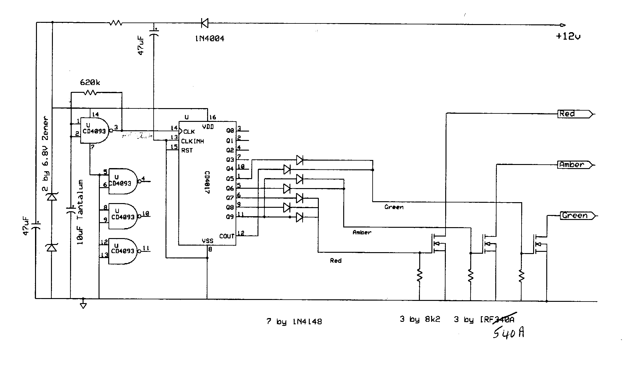
Traffic Signal Project
The proposed circuit design involves a power supply board capable of accepting a 120V AC input and converting it into multiple regulated outputs. The primary input will be connected to a transformer or a switching power supply module designed to handle 600 watts of power. This input stage will ensure that the board can safely manage the incoming voltage and current levels.
The output section will consist of at least three independent channels, referred to as outputs A, B, and C, each capable of delivering up to 200 watts at 120 volts. Each output will require individual regulation to maintain voltage stability under varying load conditions. This can be accomplished using linear regulators or switching regulators, depending on efficiency requirements and thermal management considerations.
To ensure safety and compliance, the design should incorporate circuit protection features such as fuses or circuit breakers on the input side to prevent overload conditions. Additionally, each output should include overcurrent protection to guard against potential short circuits or excessive load draws.
The layout of the board should facilitate adequate heat dissipation, especially near the voltage regulation components, as they will generate heat during operation. Proper thermal management strategies, such as heat sinks or active cooling solutions, may be necessary to maintain optimal operating temperatures.
Furthermore, appropriate filtering capacitors should be placed at the output terminals to minimize voltage ripple and provide stable power to connected devices. The overall design must adhere to relevant electrical standards and safety regulations to ensure reliable operation and user safety.
This schematic will require careful component selection, including transformers, rectifiers, capacitors, and voltage regulators, to meet the specified performance criteria while ensuring durability and reliability throughout its operational life.I would like to build a board that has 1 - 120volt/600Watt input and > 3 - 120volt/200Watt outputs. The outputs we shall call A, B .. 🔗 External reference
Related Circuits
This signal generator is designed for the realignment of radio receivers. The unit is inexpensive and relatively simple but adequately serves its intended purpose. However, the output is not a pure sine wave, which may make it unsuitable for...

An audio filter is positioned at the input of each audio integrated circuit (IC) chip to filter the audio signal intended for speakers. A low-pass filter is utilized for the woofer, while a high-pass filter is employed for midrange...
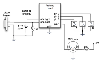
The notes for the fourth and final class are available on the Spooky Arduino class page. At the conclusion of the class, Mark from Machine Project awarded each student a merit badge. A project utilizing techniques from this week's...
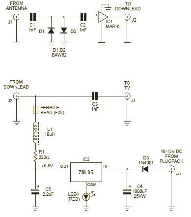
This wideband amplifier circuit is designed using the MAR-6 IC manufactured by Mini Circuits. The MAR-6 VHF-UHF wideband amplifier circuit provides a stable gain of at least 9 dB up to 2 GHz. Since the MAR-6 is designed to...

Personal safes are innovative locking storage solutions that open with a simple touch of a finger. These devices are designed as secure storage options for medications, jewelry, firearms, documents, and other valuable or potentially hazardous items. They employ fingerprint...
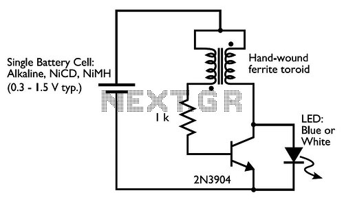
Drive a blue or white LED from a low voltage. Typically, lighting a blue or white LED requires a voltage of 3 to 3.5 V, which can be supplied by a 3 V lithium coin cell. However, a 1.5...