
Transistor attenuation - feedback tone circuit
The feedback attenuator circuit detailed in Figure 4-11 serves as a sophisticated audio processing tool, integrating various control mechanisms to enhance sound quality and user experience. The use of a 24V power supply is critical, as it allows for higher headroom and reduced distortion across the audio spectrum. The differential amplifier configuration is essential for maintaining a high signal-to-noise ratio, which is crucial for high-fidelity audio applications.
The interaction between the volume control potentiometer and the loudness control potentiometer (P7) is particularly noteworthy. This design allows for a seamless adjustment of loudness without introducing significant distortion, thus preserving the integrity of the audio signal. The attenuation process through RPi and the subsequent impedance transformation via VTi ensures that the signal maintains its quality as it passes through the tone control circuitry.
The telepresence control (RP2) offers versatility in sound shaping, enabling users to adjust the presence of mid-range frequencies, which can significantly affect the perceived clarity and detail of the audio. The subwoofer control (RP3) is designed to manage low-frequency output effectively, ensuring that bass response is both impactful and controlled, particularly during dynamic musical passages.
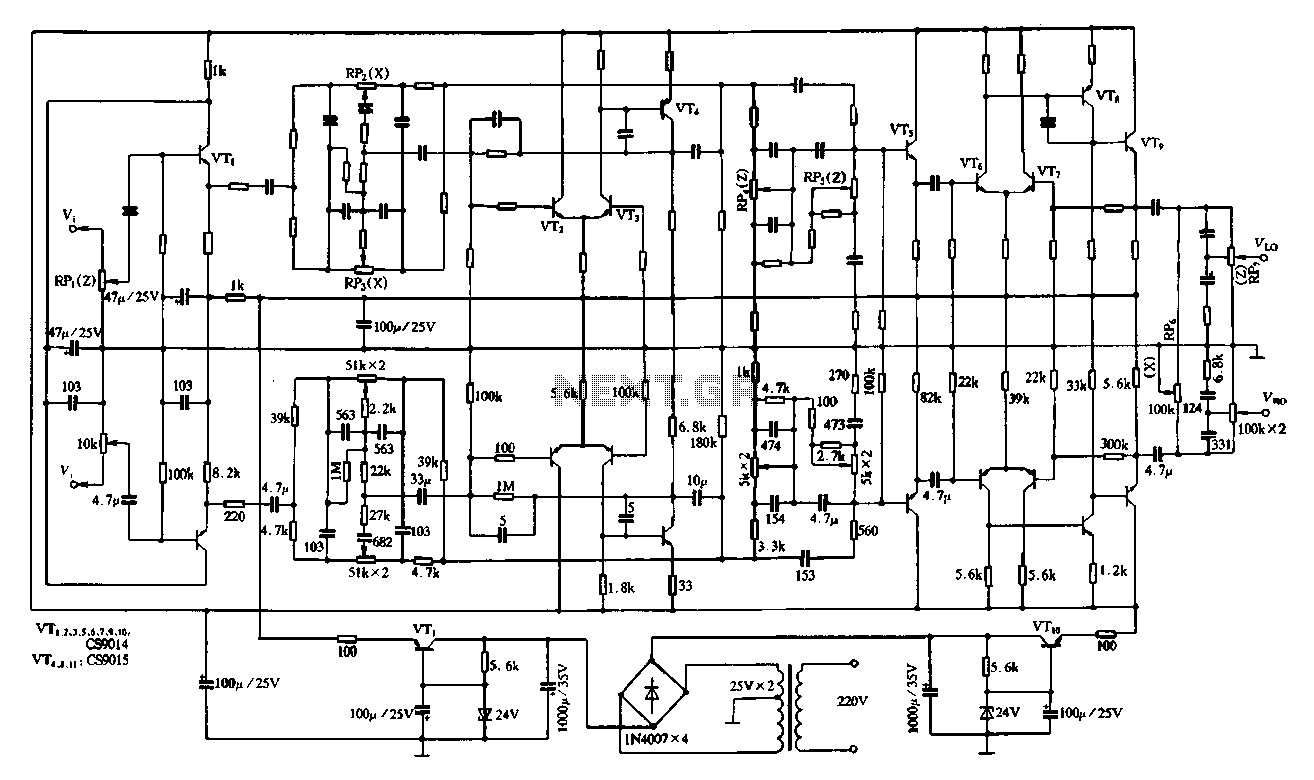
In addition, the bass control potentiometer (RP4) and treble control potentiometer (RPs) provide further customization options, allowing users to tailor the audio output to their preferences. This comprehensive control scheme enables a high level of audio fidelity and personalization, making the feedback attenuator circuit an invaluable component in advanced audio systems. Overall, the circuit exemplifies a well-engineered approach to audio processing, balancing complexity with user-friendly controls for optimal sound reproduction.Figure 4-11 is a feedback attenuator consisting of transistors tone control circuit. The circuit in addition to a conventional high, bass control system, balance control, volum e control loudness, but also with subwoofer control, field sense of control. In order to improve the transient characteristics of the entire tonal system and reduce distortion, this circuit uses a high operating voltage, 24V supply voltage. In the circuit node configuration using the excellent performance of the differential amplifier circuit as a signal to noise ratio of the circuit, the dynamic range to achieve a higher level of technology.
In the circuit, coral, volume control potentiometer is pre-din, and its subsequent stage loudness volume control potentiometer P7 brush with each other, can obtain better compensation effect of loudness while enhancing the ability to overdrive the input stage and improve playback signal to noise ratio. After the signal from the input stage by RPi attenuation through the emitter VTi constituted after the output impedance transformation, namely into the NF type tone circuitry for processing o foot) 2 as telepresence control potentiometer capable of 500 ~ 2000Hz frequency signal within the boost or attenuation around 6 f8dB, can be used to control the system and the atmosphere, increased presence.
RP3 control potentiometer for the subwoofer, it is generally the bass controller is different in frequency from the control to its lower turning point made about 100Hz. So when playing a larger dynamic music, the bass and soft but with a touch. After the feedback tone control circuit is changed after a group of straight bass High attenuation control circuit.
RP4 bass control potentiometer, it subwoofer control potentiometer RP3 can better control with low frequency interest, especially in the low frequency response of. RPs for the treble control potentiometer. The proper use of the controller, can effectively improve the clarity of the program.
Related Circuits
The photocell photoelectric tracking circuit is configured with two identical photoelectric cells that serve as light-receiving devices. When the incident light intensity is equal, the system is able to track in a predetermined manner. If there is a slight...
In a complete circuit, there are two types of elements: active and passive elements. Active elements generate energy, while passive elements dissipate energy. Examples of passive elements include resistors and capacitors. In electronic circuits, active and passive components serve distinct...
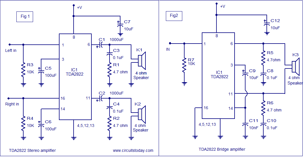
The TDA2822 audio amplifier circuit provides 1.35W output into a 4-ohm speaker when powered by a 6V supply. It supports both bridge and stereo modes and operates within a supply voltage range of 3V to 15V, making it suitable...
The schematic diagram is straightforward. SW1 is a pushbutton used to start the timer. The outputs are set to logic level 0 when the timer is inactive and to logic level 1 when the timer is triggered. The relay...
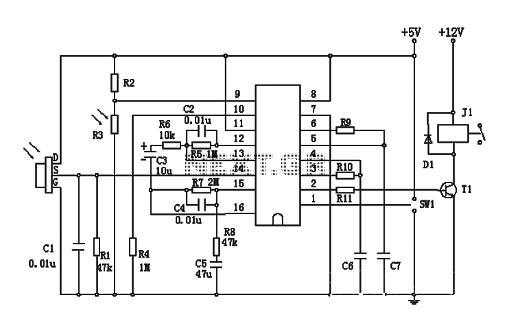
The BISS0001 is a high-performance integrated circuit designed for sensor signal processing. When combined with pyroelectric infrared sensors and a minimal number of external components, it forms a passive pyroelectric infrared switch. This device can automatically and quickly activate...
A simple CATV upstream fiber optic receiver utilizes DC pilot automatic gain control (AGC). Upstream fiber links in a community antenna television (CATV) system are often challenging to align correctly. Set-top boxes and cable modems use "long-loop" AGC. Additionally,...
Warning: include(partials/cookie-banner.php): Failed to open stream: Permission denied in /var/www/html/nextgr/view-circuit.php on line 713
Warning: include(): Failed opening 'partials/cookie-banner.php' for inclusion (include_path='.:/usr/share/php') in /var/www/html/nextgr/view-circuit.php on line 713