
A circuit of a pyroelectric infrared switch application BISS0001
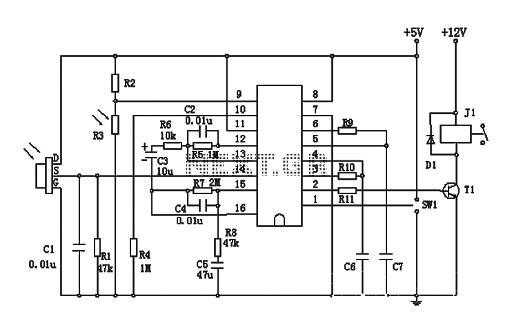
The BISS0001 circuit operates by utilizing the pyroelectric infrared sensor to detect motion or heat changes in its environment. This is achieved through a two-stage amplification process where the signals from the sensor are first amplified by OP1, then further processed by OP2. The dual comparators, COP1 and COP2, ensure that only significant changes in the detected signal are passed through as trigger signals, effectively filtering out noise and irrelevant fluctuations.
The use of a photosensitive resistor (R3) adds an additional layer of functionality, allowing the system to adapt based on ambient light conditions. This feature is particularly useful for automatic lighting applications, as it prevents the system from activating in well-lit conditions, thereby conserving energy and reducing unnecessary wear on the connected devices.
The gain of the operational amplifiers can be fine-tuned using resistor R6, allowing for flexibility in circuit design based on specific application requirements. The choice of resistor values and capacitor sizes for the timing components (R9, R10, C6, and C7) directly influences the response time and delay characteristics of the system, enabling customization for different operational scenarios.
Overall, the BISS0001 integrated circuit provides a versatile solution for automatic control applications, combining sensor technology with intelligent signal processing to enhance user convenience and energy efficiency in various environments.BISS0001 is a sensor signal processing with higher performance integrated circuits, which together with the pyroelectric infrared sensors and a small amount of external components constitute passive pyroelectric infrared switch. It can automatically and quickly open various types of incandescent, fluorescent, buzzer, automatic doors, electric fans, dryers and automatic sinks and other devices, especially for enterprises, hotels, shopping malls, warehouses and family aisles, corridors and other sensitive area, or automatic lighting, lighting and alarm systems for the security zone.
FIG R6 can adjust the size of the gain of the amplifier, the original drawings selected 10K, actual use can 3K, can improve the gain of the circuit to improve circuit performance. Output delay time Tx by an external R9 and sizing C7 triggered by an external blocking time Ti R10 and C6 resizing, R9 / R10 470 ohms may be used, C6 / C7 can choose 0.1U.
Related Circuits
The circuit diagram of an IC Controlled Emergency Light with Charger, also known as a 12V to 220V AC inverter circuit, is presented here. This circuit features automatic activation of the light during mains failure and includes a battery...
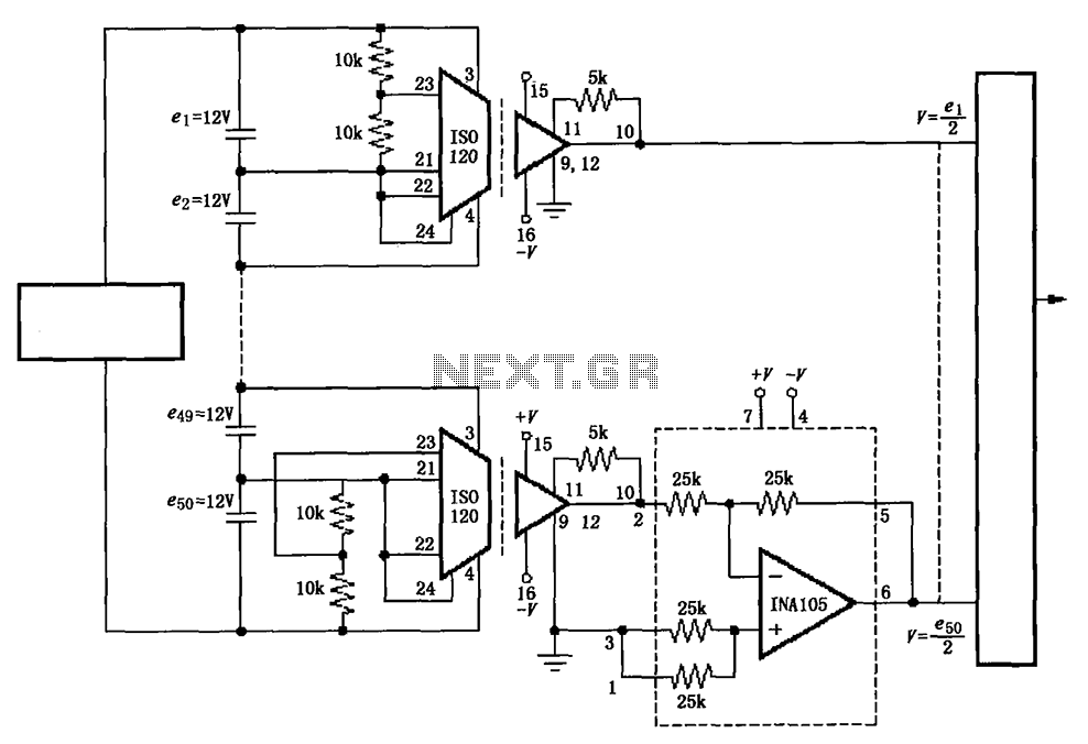
The circuit utilizes the ISO120 and INA105 instrumentation amplifiers to create a battery monitoring system for a 600V battery setup composed of 50 series-connected 12V batteries. This circuit is designed to detect charging and discharging conditions to prevent overcharging...
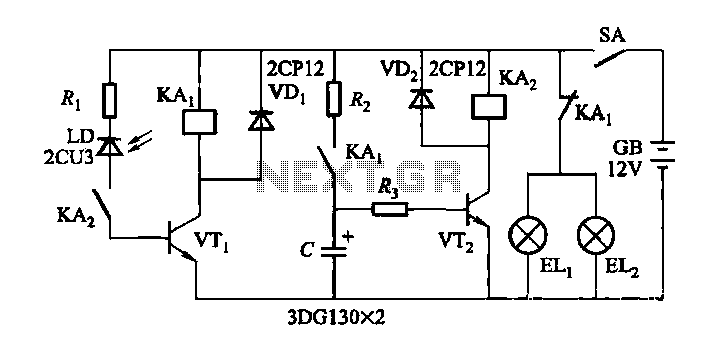
When driving at night and approaching another vehicle, traffic regulations dictate that the distance between the two vehicles should be maintained. This is achieved by alternately activating and deactivating the high beams, while utilizing either the wide lights or...
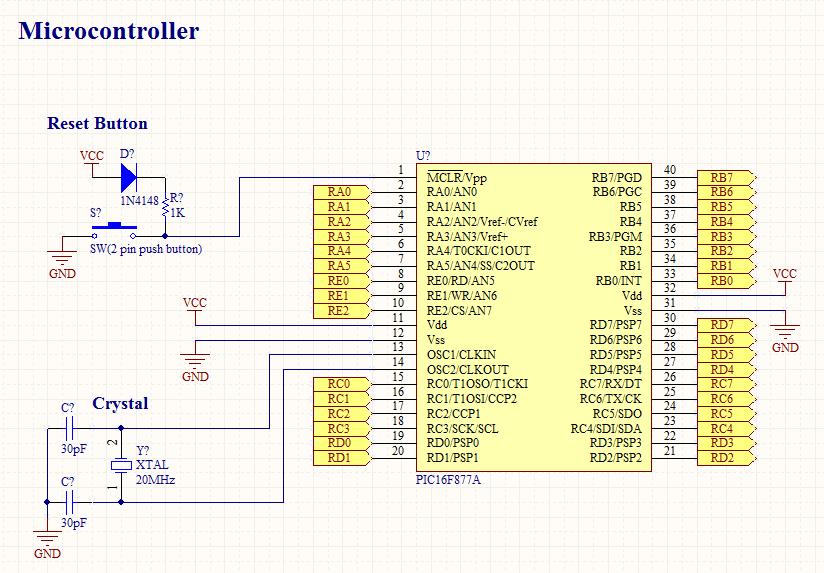
To operate a microcontroller, basic components are required to support its functionality, which is referred to as a basic circuit. The components needed are common and readily available at any electronics store. This document presents the schematic of a...
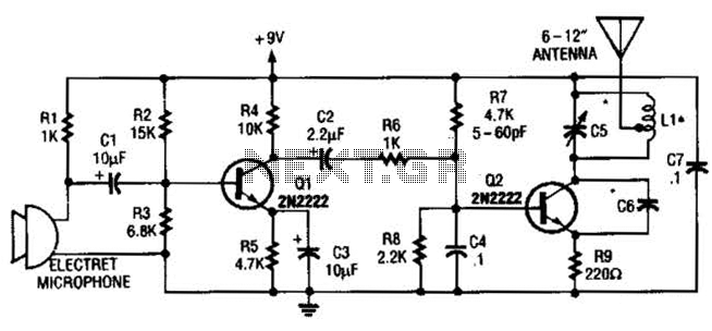
The vacuum tube remains relevant and functional in certain applications, such as in this continuous wave (CW) transmitter. The circuit is constructed in a traditional breadboard style on a wooden base. Old table radios serve as a valuable source...
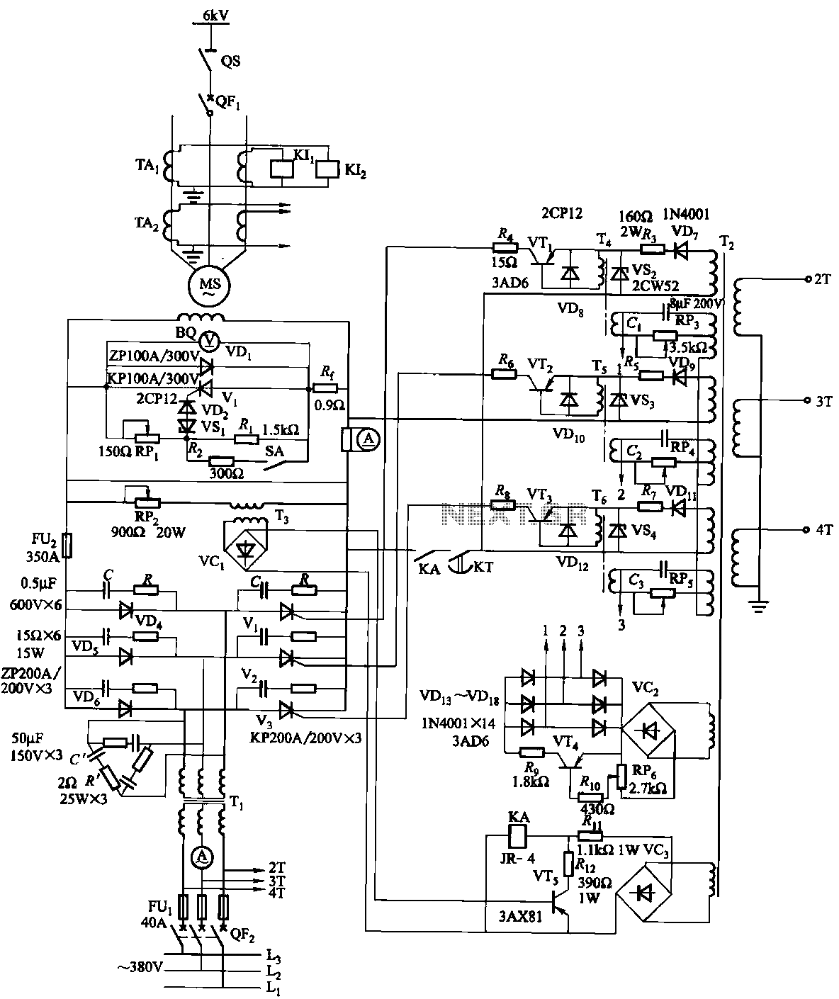
The excitation device for a light-duty synchronous motor rated at 625 kW has been initiated. The triggering circuit of the device consists of three identical RC phase-shift flip-flops. Adjustment potentiometers RP3 to RPs are used to set the RC...
Warning: include(partials/cookie-banner.php): Failed to open stream: Permission denied in /var/www/html/nextgr/view-circuit.php on line 713
Warning: include(): Failed opening 'partials/cookie-banner.php' for inclusion (include_path='.:/usr/share/php') in /var/www/html/nextgr/view-circuit.php on line 713