
Transistor Tester
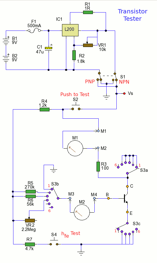
The circuit is designed to evaluate the current gain characteristics of low to medium power transistors by measuring both the small signal hfe and the DC current gain hFE. The hfe, or small-signal current gain, is defined as the ratio of the output current to the input current in the active region of a transistor, while hFE represents the DC current gain in a specific operating condition.
The measurement setup typically includes a transistor under test, a variable resistor to set the base current, and a multimeter to measure the collector current. The circuit operates by applying a known base current to the transistor and measuring the resulting collector current, allowing for the calculation of both hfe and hFE.
To perform the measurement, the following steps are generally taken:
1. Connect the transistor to the circuit, ensuring that the emitter, base, and collector terminals are correctly identified and connected.
2. Adjust the variable resistor to establish a specific base current, which can be varied to observe the transistor's response.
3. Measure the collector current using the multimeter, ensuring that it is set to the appropriate current range for accurate readings.
4. Calculate the hfe using the formula: hfe = Ic/Ib, where Ic is the collector current and Ib is the base current.
5. For hFE, the measurement is taken under DC conditions, typically at a fixed collector-emitter voltage, allowing for a different operational perspective of the transistor's gain characteristics.
This circuit is beneficial for testing and characterizing transistors in various applications, ensuring that they meet the required specifications for integration into electronic designs. Proper understanding and measurement of these parameters are crucial for optimizing circuit performance and reliability.This circuit can measure both small signal hfe and DC current gain hFE of a low to medium power power transistor.. 🔗 External reference
Related Circuits
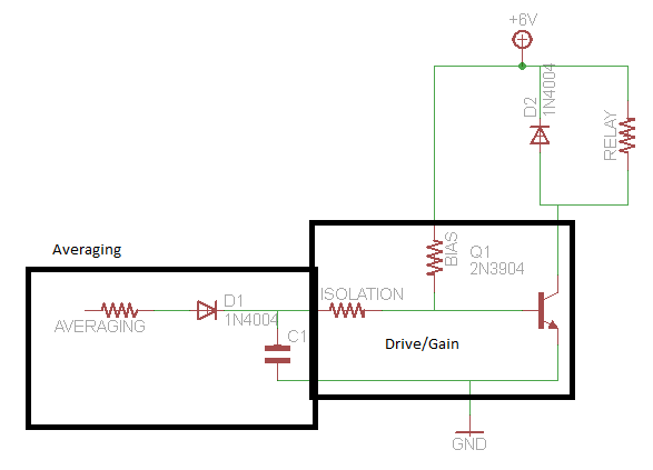
A circuit that activates a relay upon detecting audio pulses from one channel of an MP3 player. The intention is to synchronize recorded audio pulses with music to control a motor for mouth movement. For a stereo player, music...
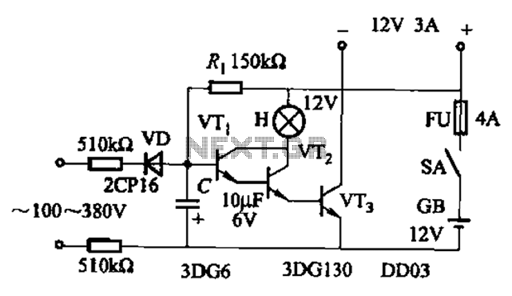
An AC-DC power supply without a power switching circuit is typically utilized for lighting load circuits. Once the power grid is restored, the standby power supply automatically switches on. An automatic switching circuit using a transistor is implemented, with...
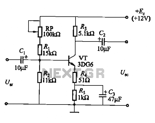
The circuit is a bias circuit for automatic stabilizers that maintains a stable quiescent operating point with good thermal stability. It utilizes a three-pole tube with an NPN type transistor, characterized by a small Iceo. An adjustment potentiometer, RP,...

The simple transistor tester in Figure 1 allows for the identification of the type of transistor and aids in detecting the emitter, collector, and base of the transistor. The simple transistor tester circuit is designed to facilitate the identification of...
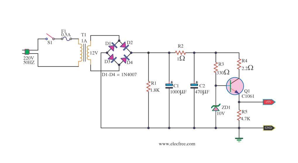
This is a DC power supply circuit designed to regulate 9 volts and provide a current output ranging from 1 amp to 2 amps. The circuit utilizes a modified TIP31 transistor, although alternative transistors such as TIP41, MJE3055, or...
This is a simple spanniningszoeker that is very suitable for car, for connection of alarm systems, handsfree kits, radios, etc. At rest, the yellow LED because the path of least resistance. If the probe with a positive or negative...