
Automotive voltage tester schematic
The described circuit functions as a voltage tester, specifically designed for automotive applications. It is capable of detecting the presence of voltage in various automotive systems, such as alarm systems, hands-free kits, and radios. The circuit operates on a 12V power supply, which is typically sourced from the vehicle's electrical system. A practical method for powering the circuit is to use a cord with a cigarette lighter plug, allowing for easy connection to the vehicle's power source.
The circuit includes three light-emitting diodes (LEDs), which provide visual feedback regarding the voltage status detected by the circuit. The yellow LED serves as an indicator of the circuit's operational state. When the circuit is at rest, this LED illuminates due to the path of least resistance. Upon connecting the probe to a positive or negative voltage source, either the red or green LED will light up, indicating the presence of voltage and effectively signaling the user that the circuit is active.
Resistors R1 and R2, both rated at 680 ohms, are employed to limit the current flowing through the LEDs, ensuring that they operate within safe limits and prolonging their lifespan. The diodes D1 and D2, specified as 1N4148, are used for signal rectification and protection within the circuit. These diodes help to prevent reverse polarity connections that could damage the circuit components.
The housing of the tester can be constructed from a standard voltage tester case, which provides a sturdy and portable enclosure for the circuit. This design not only ensures the durability of the tester but also facilitates ease of use in automotive environments. Overall, this simple spanniningszoeker is an effective tool for automotive technicians and enthusiasts alike, enabling quick and reliable voltage detection in various applications.This is a simple spanniningszoeker that is very suitable for car, for connection of alarm systems, handsfree kits, radios, etc. At rest, the yellow LED because the path of least resistance. If the probe with a positive or negative pole connected is coming and the red or green and yellow LED light goes out.
The yellow LED also serves as a check or put pressure on the circuit state. The circuit has a 12 V power supply just that the car is tapped. The best you can do with a cord with a cigarette lighter plug on it. The housing of the tester itself, for example the case of a standard voltage tester. R1, R2 = 680 ? D1, D2 = 1N4148 D3-D5 = LED, yellow, green, red 🔗 External reference
Related Circuits
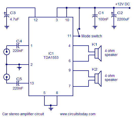
A car stereo amplifier circuit that can be used in automobiles, designed using the Class-B audio amplifier TDA1553, complete with a circuit diagram and schematics. The car stereo amplifier circuit utilizes the TDA1553, a Class-B audio amplifier known for its...

The system employs an optical fingerprint sensor utilizing the ARM Cortex M3 core, specifically the STMicroelectronics 32-bit high-performance microcontroller STM32F205RE. It incorporates a function body composition that utilizes the Sobel edge detection operator, Gabor filtering, image binarization, and various...
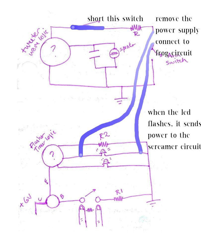
An arrangement was established that functions effectively. In the siren circuit, the reed switch was shorted as illustrated. The power supply was removed, and a new configuration was created. The described siren circuit utilizes a reed switch, which is a...
This circuit measures the distance covered during a walk. The hardware is housed in a compact box that can be conveniently placed in a pants pocket. The display is designed as follows: the leftmost display, D2 (the most significant...
This project involves a straightforward soil moisture detection circuit that utilizes only four components and operates with a 3-volt battery. The circuit is designed to identify the presence of moisture in the soil of any plant and activate an...
L2 RFC (resistance 1MOhm with an inductor wrapped around it, composed of multiple coils made from fine insulated wire. The scratch of the inductor connects to the resistance, forming a parallel L-R circuit.) With capacitors C7 and C8, we...
Warning: include(partials/cookie-banner.php): Failed to open stream: Permission denied in /var/www/html/nextgr/view-circuit.php on line 713
Warning: include(): Failed opening 'partials/cookie-banner.php' for inclusion (include_path='.:/usr/share/php') in /var/www/html/nextgr/view-circuit.php on line 713