
Night Light schematic

```c
void timer_isr(void) interrupt 1 using 1 {
TH0 = 0x8b;
TL0 = 0x7f; // reload with 35711 for 10Hz tick
tick_test = 1; // test tick for 10Hz/2 or 5Hz
time();
set_time();
blink_led();
update_output();
}
main() {
TMOD = 0x01; // timer1 and timer0 = mode 1
EA = ET0 = TR0 = 1; // enable timer0 interrupt, start timer
PCON |= 1; // enable IDLE mode to extend backup period
for(;;);
}
```
Figure 4 illustrates that pressing SW2 sets the start time at 18:00, causing the lamp to turn on until 22:00 daily. The preset time of 18:00 can be adjusted by pressing SW2 at the desired time; for instance, if the time is set to 19:00 in summer when the sun sets later, the lamp will turn on at 19:00 the following day, with the time off shifting to 23:00.
The schematic demonstrates a robust design for a night light saver, integrating power management, timing functions, and user interaction through simple switch controls. The use of a microcontroller allows for flexible programming and adaptability to user preferences, making it a versatile solution for automated lighting control.The complete hardware schematic of the Night Light Saver V6. 0. The AC line was protected F1, a 1A fuse. Any short circuit caused by saver`s components will blow the fuse. R1 and C1 limit current to the +5V zener diode, D3. R2 discharges capacitor C1 when power terminal of the circuit was opened. The super capacitor C2, +5V 0. 01F filters DC supply. D4 acts as unidirectional switch for current supplied to MCU. BT1 is +3V 60mAH Ni-MH battery for backup the MCU when main power failed. The charging current is approx. 2mA with AC main lives. When main power failed, BT1 supplies approx. 4mA to the MCU. With fully charged, it could be able to provide backup time approx. 15Hrs. The MCU runs with +Vbackup. SW1 helps reset the MCU, in case of brownout voltage by BT1. C4 and internal pull-down resistor forms simple reset circuit. The MCU, 89C2051 runs with 3. 579MHz Xtal. SW2 is for clock setting, when pressed, time will be 18:00. P3. 7 drives tick LED with small sink current. R5, 4. 7k limits less than one mA for D5. P3. 0 provides 5Hz clock signal for calibration. The output bit is P1. 6. It drives PNP transistor, Q1. R3 limits base current. R5 pull base pin to +V when P1. 6 is logic `1` to fully turn off Q1. R4 limits DC current injected to Q2, MAC97 small triac. LP1 is incandescent 25W lamp. The lamp`s wattage can be up to 40W. The source program is beautiful coding with c language. After timer initialization then idle mode is entered by setting bit0 in PCON register. The timer0 overflows 10 times per second. Tasks for update clock, check SW2, blink LED and update output bit will be executed every 1/10s. The task that controls output instead, will be executed every one second. For different preset time, time on, time off, you can edit the source code and recompile with sdcc easily. I provide sample scheduler scanning function, scan_pgm( ). If you want to modify the code for all 8-bit output on P1 similar to the Miniature Real-time Controller.
You may have open collector driver, the same hardware and modify a little bit of the source code. void timer_isr(void) interrupt 1 using 1 { TH0 = 0x8b; TL0 = 0x7f; // reload with 35711 for 10Hz tick+; tick_test = 1; // test tick for 10Hz/2 or 5Hz time(); set_time(); blink_led(); update_output(); } main() { TMOD = 0x01; // timer1 and timer0 = mode 1 EA = ET0 = TR0 = 1; // enable timer0 interrupt, start timer PCON |= 1; // enable IDLE mode, to extend backup period for(;) ; } Figure 4 shows start time at 18:00 when SW2 was pressed. The lamp will turn on until 22:00 everyday. Since the preset time, 18:00 can set whenever SW2 was pressed, so if you want to change time on, for examples in summer season, sun will set lately, suppose you want the lamp to be turned on at 19:00, you just press SW2 at 19:00.
The day after it will turn on at 19:00, however time off will shift to 23:00. 🔗 External reference
Related Circuits
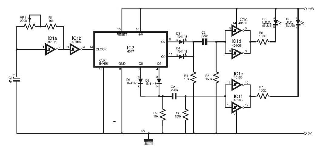
This circuit simulates the flashing lights of a police car, similar to those seen on British police vehicles. The operational amplifier IC1a functions as a square wave oscillator, with an adjustable frequency controlled by the variable resistor VR1 to...
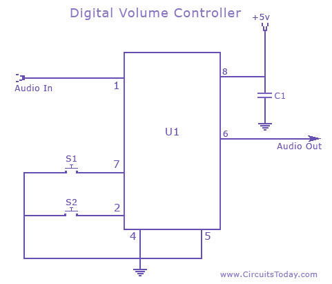
A digital volume control circuit diagram utilizing the DS1669, a potentiometer integrated circuit. This circuit can serve as a digital volume controller for audio amplifiers and various other applications. The digital volume control circuit employs the DS1669 integrated circuit, which...
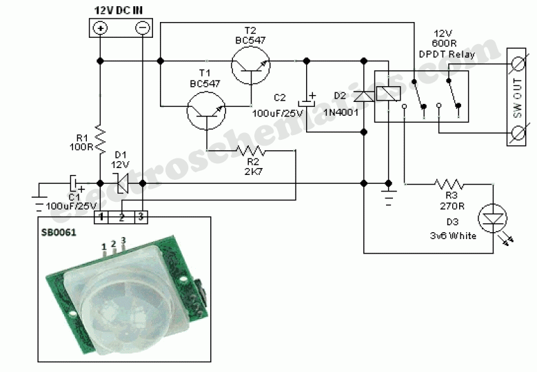
This circuit represents a general-purpose white LED security light equipped with a Passive Infrared (PIR) motion sensing mechanism. The core component of the circuit is the PIR sensor module SB0061, which is a pyroelectric sensor designed for human body...
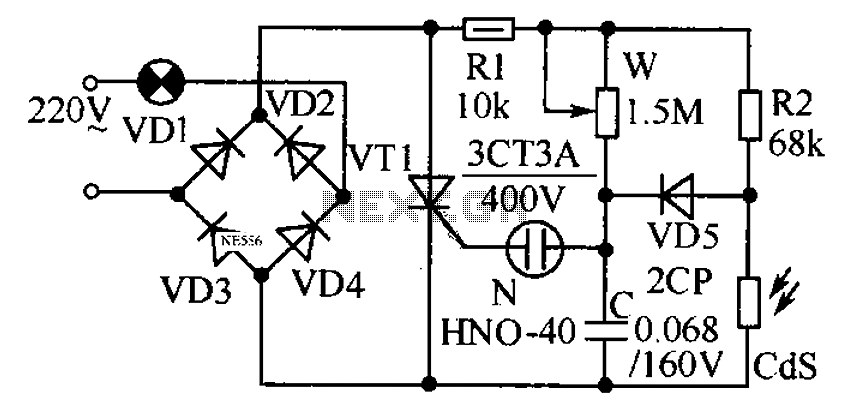
This circuit is designed to automatically adjust the brightness of lights based on the ambient light intensity. In bright conditions, the lights remain off, while in low ambient brightness, the lights are activated. The circuit incorporates a thyristor (VT1)...
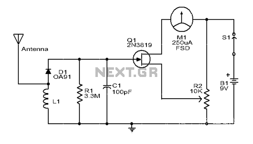
This is a simple and low-cost broadband high-frequency electric field strength meter. The field strength of the radio signal is converted into a DC measurement for analysis. The signal is captured by a coil and processed through a diode...
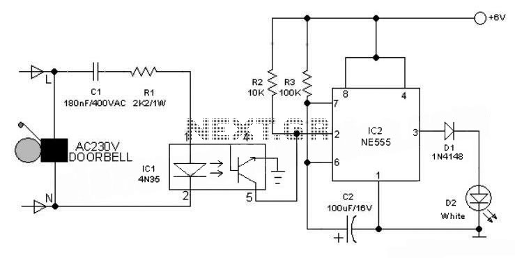
This 6V battery-operated doorbell light circuit can be connected in parallel with any existing AC 230V doorbell. When the doorbell switch is pressed, the bell sounds as usual, and the AC mains supply available across the doorbell is routed...