
Transmitter Negative Key Line Keyer

The circuit utilizing the NTE288, ECG288, GE223, or SK3434 is designed to control a negative voltage line, capable of handling up to -300 V. This high-voltage switching capability is particularly useful in applications where a negative voltage needs to be selectively activated or deactivated, such as in certain types of power supplies or signal processing circuits.
Key components of the circuit include the NTE288 transistor, which serves as the primary switching element. This transistor is designed to handle high voltages and can effectively control the flow of current to the load connected to the negative line. The circuit should be configured with appropriate biasing and protection components to ensure reliable operation. For instance, a resistor may be placed in series with the base of the transistor to limit the base current, and a diode may be included to protect against back EMF if inductive loads are involved.
It is critical to note that this circuit is not suitable for keying vacuum-tube amplifiers that draw grid current. In such applications, the keying transistor may be subjected to conditions that exceed its rated specifications, leading to potential damage. Therefore, careful consideration should be given to the load characteristics and operating conditions when implementing this circuit.
In addition to the transistor, the circuit may require additional components such as capacitors for decoupling, resistors for biasing, and possibly a zener diode for voltage clamping to protect the transistor from overvoltage conditions. Proper layout and thermal management should also be considered to ensure the reliability and longevity of the circuit under high-voltage operation.
Overall, this circuit provides a robust solution for controlling high negative voltages, provided that it is used within its specified limits and with consideration for the load characteristics. Using an NTE288 (or ECG288, GE223, or SK3434), this circuit can key a negative line up to - 300 V maxim um. Do not use this circuit to key a vacuum-tube amplifier that draws grid current because the keying transistor might be damaged under these conditions.
Related Circuits
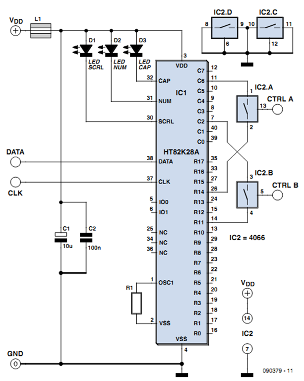
One of the more challenging aspects of creating a control or security system that utilizes a PC, such as a burglar alarm, is connecting the sensors to the computer. This typically requires specialized interface expansion boards, and programming that...
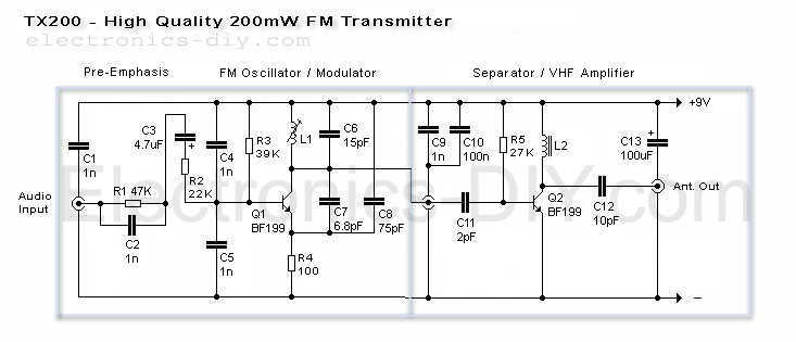
Here is the latest and greatly improved TX200 VFO/VCO FM transmitter. The most versatile transmitter to date that can be turned into high fidelity stereo PLL based 200mW FM transmitter. It is a perfect circuit for transmitting your music...
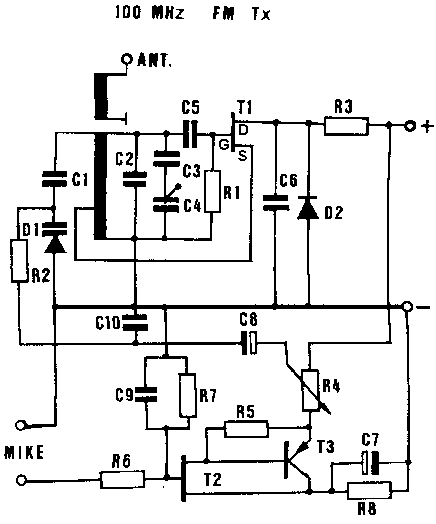
This ZIP file contains information about building a small radio transmitter, which has a PCB 1.75" x 2.5" (45mm x 68 mm) and has a range of about 30 yards or so. The documentation with the circuit says the...
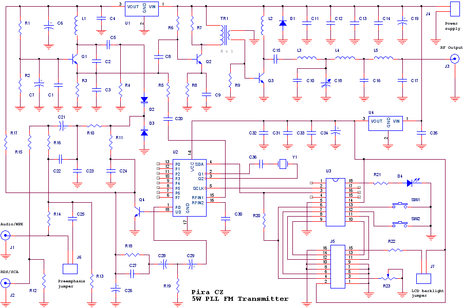
The transmitter includes RDS/SCA input and Audio/MPX input with optional preemphasis. It can be used with or without stereo encoder. Tuning over the FM band is provided by two buttons that control dual-speed PLL. The transmitter can work also...
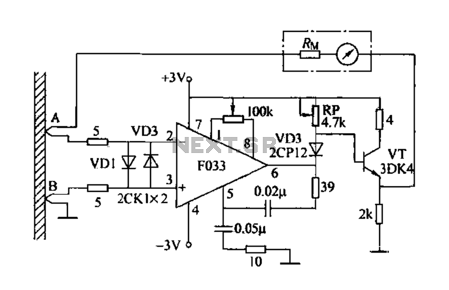
Detecting electrical equipment sometimes requires disconnecting the circuit in series for more accurate measurements of electrical current using an ammeter. However, restoring the circuit to its original state is necessary, as it can affect the normal operation of electrical...
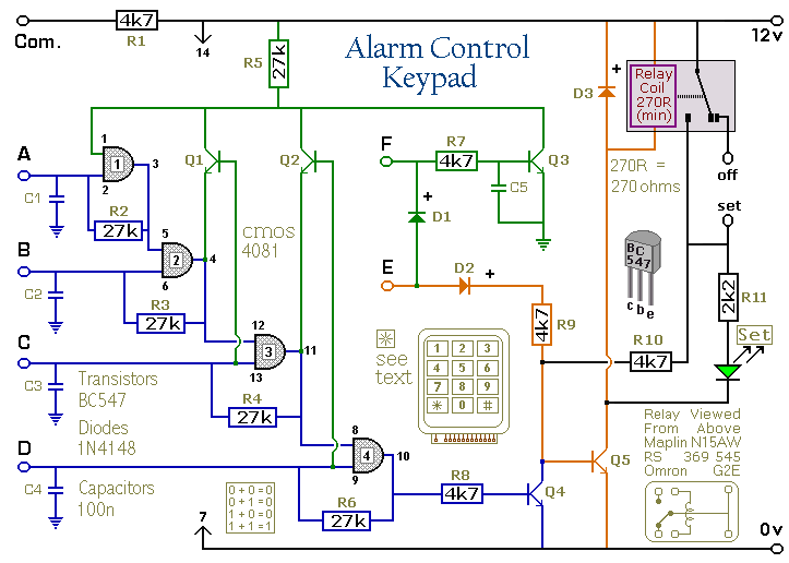
Pressing a single key on the keypad energizes the relay. Entering a four-digit code of your choice de-energizes the relay. The circuit was designed to control the Modular Burglar Alarm System but can have other applications. A five-digit version...