
control interface via pc keyboard
The proposed circuit leverages the existing infrastructure of a standard keyboard to interface with various sensors, thereby simplifying the connection process. The use of the CD4066 analog switch IC allows for the seamless integration of sensor inputs without the need for complex programming or additional hardware. Each sensor can be configured to trigger a specific key press, thus enabling a straightforward method for the PC to interpret these signals as commands.
In practical implementation, it is essential to ensure that the sensors provide a clean digital signal compatible with the CD4066's input requirements. The power supply for the circuit can be derived from the keyboard itself, which typically operates at 5 volts, making the entire setup energy-efficient. The design can be adapted to various applications beyond security systems, such as automation tasks, where multiple sensors may control different functions on a PC or other electronic devices.
The flexibility of this approach allows for scalability; additional CD4066 ICs can be added to accommodate more sensors, and the keyboard matrix can support numerous configurations. Each sensor's activation can be tailored to specific keys, allowing for a wide range of control options. This method not only reduces costs associated with specialized hardware but also simplifies the overall design, making it accessible for various applications in home automation and security.One of the more difficult aspects when making a control or security system that uses a PC (a burglar alarm using a PC, for example), is the connection of the sensors to the computer. In addition to typically requiring specialist interface expansion boards, the writing of the program that includes interrupts is often also an insurmountable obstacle.
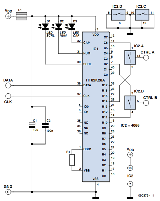
But when only a simple system is concerned consisting of, for example, four light barriers or, if need be, trip wires giving a digital on/off signal when uninvited guests enter, then a much cheaper but nevertheless effective interface is possible. For this interface we use an (old) computer keyboard. This contains as many switches as there are keys. These switches are scanned many times per second in a matrix in order to detect the potential press of a key.
The number of columns is usually eight (C0 C7 in the schematic); the number of rows varies for each type of keyboard and can range from 14 to 18 (R0 R17 with the H T82K 28A keyboard encoder mentioned in the example). To each switch there is a single column and a single row connection. The intention of the circuit is that sensor A will push` the letter A, when it senses something. This requires tracing the keyboard wiring to figure out which column and which row is connected to the A key.
One of the four analogue switches from the familiar CD4066 CMOS IC is then connected between these two connections; that is, in parallel with the mechanical A key on the keyboard. When the Control-A input of the CD4066 is activated by sensor A, the letter A will be sent to the computer by the key-board.
The PC can then act appropriately, for example by entering the alarm phase. The system is not limited to (burglar) detection using a PC. The remote control of a TV set or other electronic devices can also be operated with a 4066 in the same way; for example to scan through a number of TV channels in a cyclical fashion. To do this, you could, for example, shunt the next channel` button using one of the 4066 switches, which itself is activated by a 1-Hz square wave generator.
In the schematic only switches A and B of the CD4066 are connected to the keyboard. You can, of course, use all four of the switches and if you need more than four you can use multiple CD4066 ICs. The indicated wiring between the keyboard IC and the 4066 is an example only, and each typed` letter has to be determined by the user for the specific keyboard that is used.
It is important that each CD4066 switch is always connected between a row- and a column connection. The output signal from the sensors has to be suitable for the CD4066 and the power sup-ply voltage of 5 volts used by the keyboard. The power supply for the CD4066 may be obtained from the keyboard. 🔗 External reference
Related Circuits
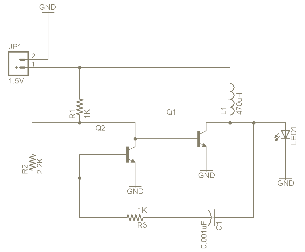
The Joule Thief is a straightforward and uncomplicated device, yet its functionality is remarkable. It can utilize a battery that is otherwise deemed unusable in any other electronic device, and it is very easy to construct on a breadboard...
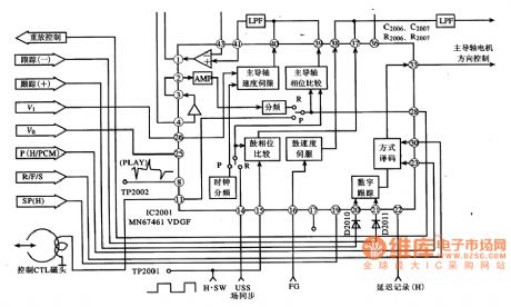
MN67641VDGF IC pin functions and data. MN67461VDGF IC's internal circuit block diagram and its typical application circuit. MN67461VDGF is a servo control IC produced by Panasonic, widely used in video cameras, such as the Panasonic NV-M8000 camera. Features: The...
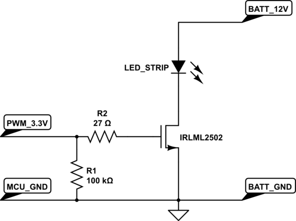
A strip of LEDs is controlled by a microcontroller using pulse-width modulation (PWM) to adjust brightness. The LED strip requires approximately 1.5A at 12V. The user, who has experience only with low-power digital electronics, seeks confirmation of their assumptions...

Utilize the Maxim MAX292 switched-capacitor filter integrated circuit to convert a square wave into a sine wave. The operational frequency range of the circuit spans from 5.2282 Hz to 8928.6 Hz when the microcontroller is functioning at a 16-MHz...
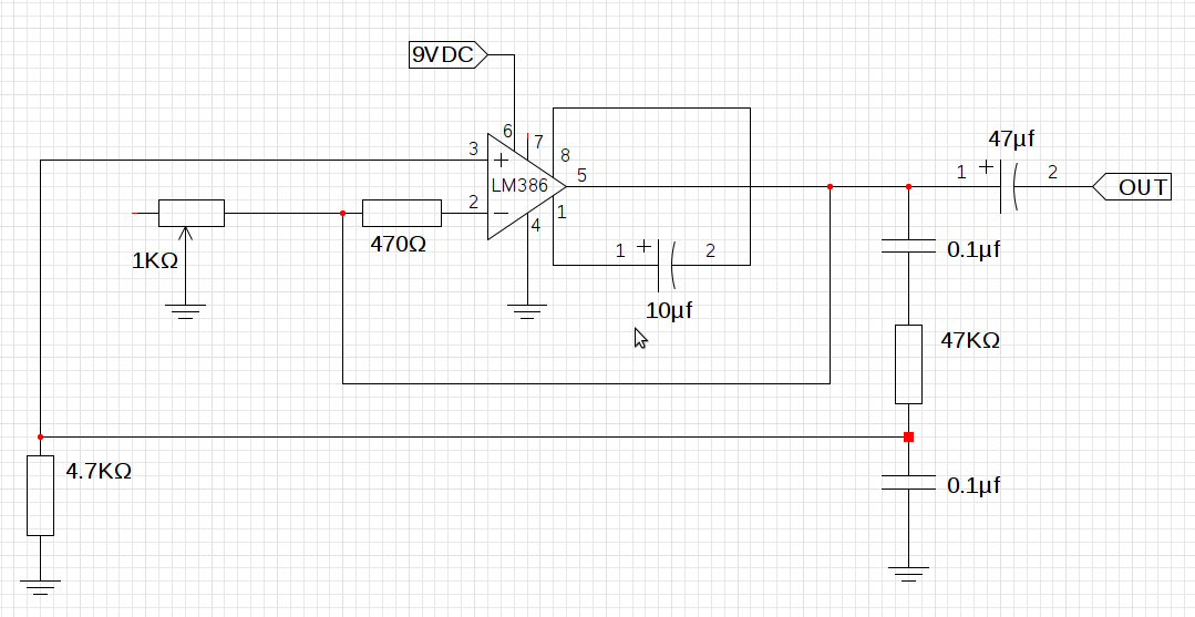
The design utilizes the LM386n-1 integrated circuit, powered by a single power supply to maintain a compact layout. There is a need to control the frequency, and the user is inquiring about which component values should be adjusted for...
The controller is a prototype and works well in my plane with 7 cells and a Graupner-Speed 600. The described controller is a prototype designed for use in a model aircraft, specifically optimized to operate with a battery pack consisting...
Warning: include(partials/cookie-banner.php): Failed to open stream: Permission denied in /var/www/html/nextgr/view-circuit.php on line 713
Warning: include(): Failed opening 'partials/cookie-banner.php' for inclusion (include_path='.:/usr/share/php') in /var/www/html/nextgr/view-circuit.php on line 713