
Tremolo

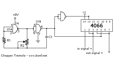
The described circuit utilizes a 4093 quad NAND Schmitt trigger to generate a clock signal, which oscillates at approximately 5 Hz when configured with the specified component values. This clock signal is essential for modulating the gain of the LM386 audio amplifier, allowing for the creation of a tremolo effect. The tremolo effect is achieved by manipulating the gain control pin (pin 8) of the LM386, which alters the amplitude of the audio signal based on the clock frequency.
To facilitate experimentation with different modulation rates, a trimmer potentiometer can be connected in series with resistor R1. Selecting R1 as 100 kΩ and the trimmer as 1 MΩ provides a versatile range of modulation frequencies, allowing for adjustments between 2 Hz and 20 Hz. This flexibility enables the user to customize the tremolo effect to their preference.
Resistor R2 is designated as the depth control, influencing the intensity of the tremolo effect. A trimmer in series with R2 allows for fine-tuning this parameter. The suggested configuration is to use a 5 kΩ resistor for R2 along with a 50 kΩ trimmer, which provides a sufficient range for depth adjustment.
Capacitor C4 plays a critical role in determining the gain of the LM386 amplifier. By selecting a larger capacitor, the gain can be increased, which enhances the overall output level of the audio signal. Conversely, a smaller capacitor will reduce the gain. It is crucial to maintain a minimum capacitance of 0.1 µF to preserve the integrity of the lower frequency response of the audio signal, ensuring that the output remains musically relevant and does not cut off essential bass frequencies.
Overall, this circuit provides a straightforward method for introducing a tremolo effect to an audio signal, with adjustable parameters for both modulation rate and depth, making it a valuable tool for audio engineers and enthusiasts seeking to enhance their sound systems.This simple circuit can color the sound coming from your audio system. Clocking for the circuit is provided by an oscillator built from one quarter of a 4093 quad NAND Schmitt trigger. With the component values shown, it will run at about 5 Hz. The clock frequency is fed to the gain control, pin 8, of an LM386 amplifier. Tremolo is produced by varying the amplifier gain. A trimmer potentiometer can be put in series with R1, to easily experiment with different rates. 1b experiment, make R1 about 100KO and use a 1-Mil trimmer. That allows frequencies from about 2 to 20 Hz to pass. Resistor R2 is the depth control. It controls the degree of tremolo. To adjust, put a trimmer in series with R2. Make R2 a 5-KO unit and use a 50-KO trimmer. Since the tremolo clock uses the gain-control pin of the amplifier, change the value of capacitor C4 in order to change the gain of the amplifier. Make C4 larger to increase the gain or smaller to decrease it. But, don"t go any lower than 0.1 11F because you"ll be cutting into the bottom-end frequency response.
Related Circuits
A tremolo is an effect unit that modulates the amplitude of the guitar signal, typically using a triangular waveform. This particular version employs a square waveform, resulting in a more abrupt, chopping effect. Such effects are prominently featured in...
This tremolo effect circuit utilizes the XR2206 and TCA730 integrated circuits, designed for electronic balance and volume regulation with frequency correction. The circuit is beneficial for stereo channels and can simulate the Lesley effect, also known as the rotating...

The tremolo circuit of the S950 is unique. The oscillator is a standard design, using half of a 12AX7. In the schematic above, the speed control is located at the lower right, the intensity control at the upper left,...
A tremolo circuit is a type of sound effect commonly utilized in guitar effect pedals. This effect is achieved by modulating the amplitude of an audio signal. The shape of the modulating signal can vary and may include square...
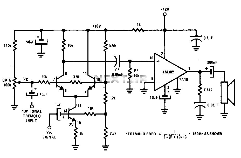
The transistors create a differential pair with an active current-source tail. This configuration, referred to as a variable-transconductance multiplier, produces an output that is proportional to the product of the two input signals. The multiplication effect arises from the...

This tremolo effect circuit utilizes the XR2206 and the TCA730 integrated circuits, which are designed as an electronic balance and volume regulator with frequency correction. The tremolo effect circuit operates by modulating the amplitude of an audio signal, creating a...