
diy tremolo effect circuit
The tremolo effect circuit is a sophisticated design that integrates multiple components to achieve a rich audio modulation effect. The XR2206 is a versatile function generator that can produce various waveforms, but its sine wave output is specifically chosen for smooth modulation characteristics. The circuit's ability to simulate the Lesley effect is particularly valuable in audio applications, providing a swirling sound that enhances the auditory experience.
Key components include the TCA730, which operates as a volume and balance regulator, allowing for precise control over the audio output. The circuit's design ensures that both channels can be modulated independently, offering flexibility in stereo sound manipulation. The linear potentiometer serves as a user interface for real-time adjustments, while the option to replace it with an AC voltage source opens up possibilities for automated modulation, adding dynamic variations to the sound.
The resistors R3, R5, and R6 play critical roles in setting the operating conditions of the sine wave generator and controlling the amplitude of the output signal. Capacitor C2 is essential for filtering out any ripple in the output, ensuring a clean audio signal. The LED indicator provides a visual representation of the modulation frequency, allowing users to monitor the effect in real-time.
The power supply considerations are crucial for maintaining stable operation. The 7815 voltage regulator is recommended to provide a consistent voltage supply, minimizing the risk of fluctuations that could detrimentally affect the modulation process. Overall, this circuit exemplifies a well-thought-out design that merges functionality with aesthetic audio effects, suitable for musicians and audio engineers looking to enhance their soundscapes.This tremolo effect circuit uses the XR2206 and the TCA730 IC which is designed as an electronic balance and volume regulator with frequency correction. The circuit is usefull for stereo channels and it also has the ability to simulate the Lesley effect aka rotating loudspeaker effect.
Balance and volume settings are done with a linear potentiomet er for both channels. If this potentiometer is replaced with an AC voltage source, a periodic modulation of the input signal can be achieved. This AC voltage source comes from the function generator IC XR2206. This IC generates square, triangle and sinewave signals but for this project we use only the sinewave.
The modulation voltage can be varied with P1 from 1 Hz up to 25 Hz. Resistor R3 sets the operation level of the sinewave generator. R5 and R6 set the DC voltage and the sinewave amplitude at the output. C2 is a ripple filter. The squarewave output of the XR2206 drives T2 and a LED to optically display the frequency. The modulating voltage reaches pin 13 of TCA730 via P3 and R10. This input functions as the volume control or in this case the volume modulation. The degree of the balance modulation (Lesley effect) can be varied with P2. A regulated power supply using 7815 IC is recommended. Do not use a non-stabilized power supply since the current variations would influence the modulation negatively. 🔗 External reference
Related Circuits
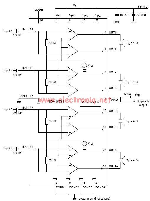
This electronic circuit diagram represents an audio power amplifier utilizing the TDA8571J integrated circuit. It is a class-B output amplifier configured in a BTL (Bridge-Tied Load) arrangement, featuring four amplifiers, each with a gain of 34 dB. The main...
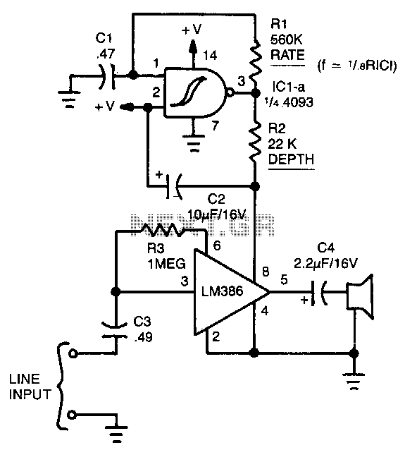
This simple circuit can color the sound coming from your audio system. Clocking for the circuit is provided by an oscillator built from one quarter of a 4093 quad NAND Schmitt trigger. With the component values shown, it will...
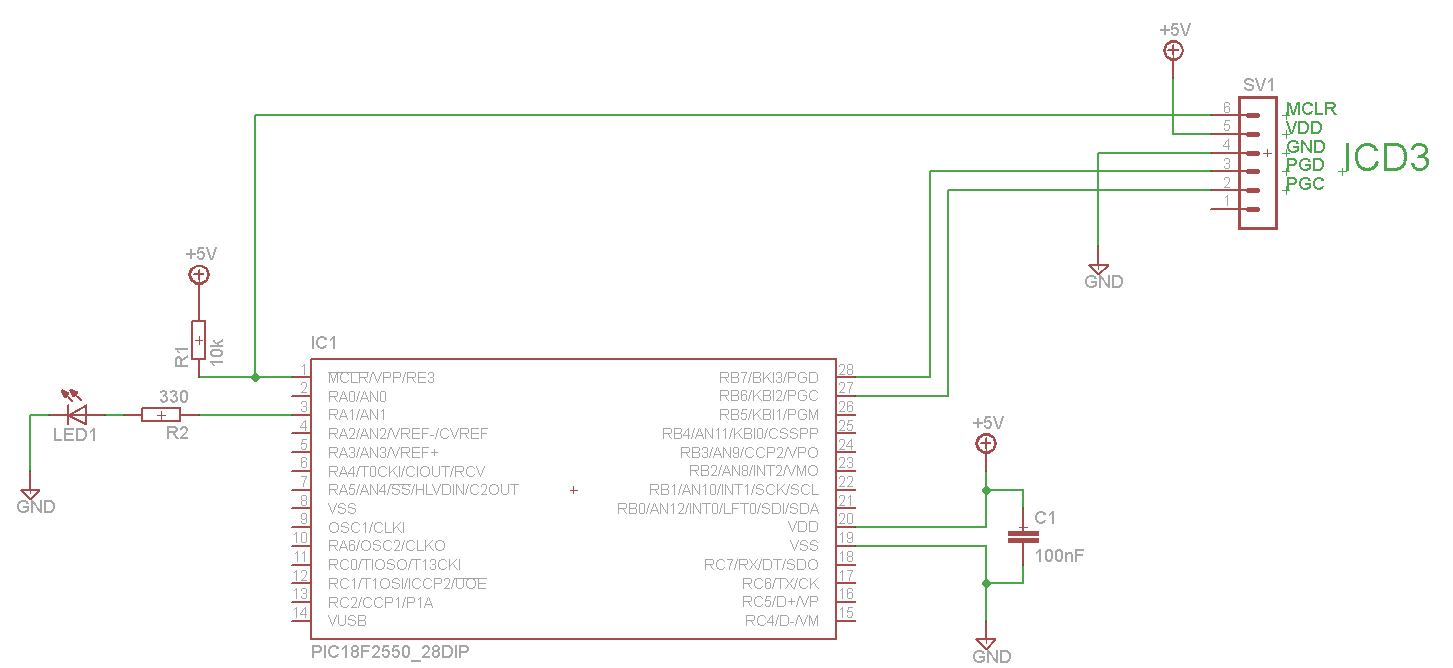
The LED blinks as expected, then pauses for an indefinite duration, flashes again a different number of times, and turns off again, displaying no discernible cyclic behavior. It activates without any external input, indicating that there is likely no...
The circuits on this page are for an Infrared Proximity Detector using the Vishay Electronics TSOP4830, which is an IR Receiver Module designed for remote control systems. The TSOP4830 functions as a sensitive infrared detector that operates without requiring...
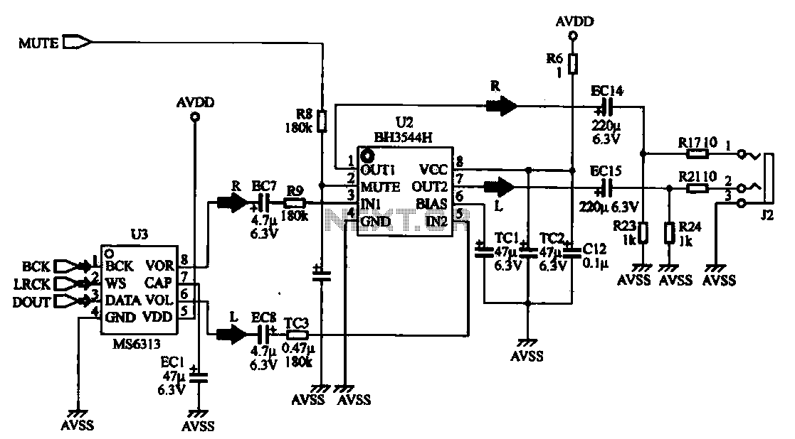
The MP4 audio circuitry consists of audio D/A converters and an audio amplifier combination circuit. This design features a straightforward circuit layout, making it suitable for integration into compact MP4 digital devices. The MP4 audio circuitry is designed to efficiently...
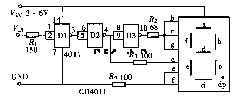
The door circuit logic pen text display can take many forms, utilizing various logic gates such as inverters, NAND gates, NOR gates, and others. A logical pen, exemplified by the NAND gate CD4011, can be used in conjunction with...