
tremolo circuit

The tremolo circuit in the S950 employs a half of a 12AX7 vacuum tube as the core component for the oscillator, which is a common design in audio effects circuits. The oscillator generates a modulating signal that varies the amplitude of the audio signal, creating a tremolo effect.
The speed control, positioned at the lower right of the schematic, allows the user to adjust the rate at which the modulation occurs. This control typically varies the frequency of the oscillator, thereby changing how quickly the tremolo effect pulses. The intensity control, found at the upper left, adjusts the depth of the modulation, influencing the extent to which the audio signal is affected by the tremolo. A higher intensity setting results in a more pronounced effect, while a lower setting produces a subtler modulation.
The output of the oscillator signal, which exits the circuit at the upper right of the schematic, is then typically routed to a mixing stage where it combines with the original audio signal. This mixing stage may involve additional components such as resistors and capacitors to shape the final output. The unique aspect of this circuit may lie in the specific configuration and interaction of these components, which can create a distinctive tremolo sound that sets the S950 apart from other devices.
In summary, the tremolo circuit of the S950 is characterized by its use of a 12AX7 tube oscillator, with clearly defined controls for speed and intensity, culminating in a unique modulation output that enhances the audio experience. The tremolo circuit of the S950 is unique. The oscillator is a standard design, using half of a 12AX7: In the schematic above, the speed control is at lower right, the intensity control upper left, and the oscillator signal leaves this picture at the upper right. What happens next is a little weird: The schematic above.. 🔗 External reference
Related Circuits
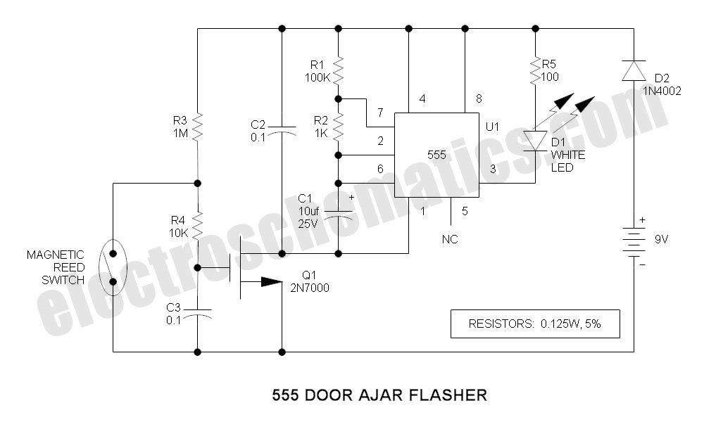
This is a compact LED flasher circuit designed using the 555 timer integrated circuit (IC), powered by two 1.5V batteries. The circuit can function as a flashing metronome, dark room timer, reminder, or for other similar applications. In the...
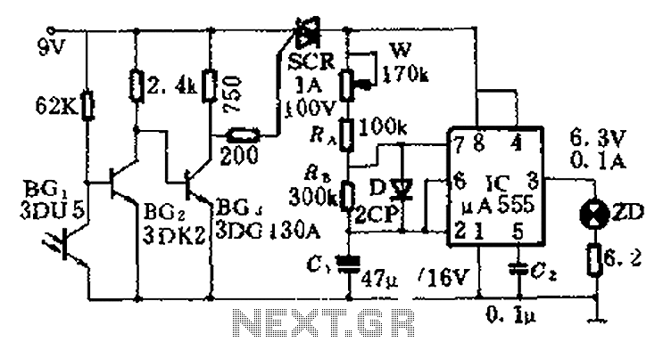
This circuit is designed for nighttime illumination and corridor lighting. During daylight, sufficient light causes BG3 to conduct, preventing the SCR from oscillating. As a result, the circuit remains inactive, and the light does not turn on. At night,...
The industrial fuel oil furnace controller circuit consists of a power supply circuit, a testing and ignition control circuit, and a control implementation circuit, as illustrated in the accompanying diagram. The power supply circuit includes a step-down capacitor (C6),...
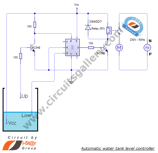
The automatic water level controller circuit is a straightforward engineering project that can automatically switch a domestic water pump on and off based on the water level in a tank. This motor driver circuit can be implemented at home...

This is a wideband high-frequency amplifier circuit designed for a frequency range between 75-150 MHz. It utilizes a PNP transistor amplifier to enhance signal strength before it reaches the receiver of devices such as phones, FM radios, or amateur...
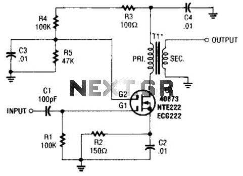
A MOSFET is utilized as a wideband buffer amplifier. T1 is wound on a toroid of approximately specified diameter, using material suitable for the frequency range, typically between 1 MHz and 20 MHz. The turns ratio should be approximately...
Warning: include(partials/cookie-banner.php): Failed to open stream: Permission denied in /var/www/html/nextgr/view-circuit.php on line 713
Warning: include(): Failed opening 'partials/cookie-banner.php' for inclusion (include_path='.:/usr/share/php') in /var/www/html/nextgr/view-circuit.php on line 713