
Triac-Construction and Operation
The triac is often represented in electronic schematics by a specific symbol that indicates its three terminals. The gate terminal, typically denoted as G, is crucial for controlling the conduction state of the triac. The application of a gate signal can be done through resistive or capacitive coupling, depending on the desired circuit behavior and the characteristics of the load being controlled.
In practical applications, the triac can be used in various configurations, including phase control for light dimmers, motor speed controllers, and heater control circuits. The choice of gate current and the timing of the gate pulse are critical parameters that affect the performance of the triac in these applications. Additionally, considerations must be made regarding the thermal management of the triac, as excessive heat can lead to failure. Heat sinks or thermal pads are often employed to dissipate heat generated during operation.
For optimal performance, the triac should be selected based on its voltage and current ratings, which must exceed the maximum expected load conditions. Furthermore, protective components such as snubber circuits may be used to safeguard the triac from voltage spikes and to enhance its reliability in various operational environments.The triac is another three-terminal ac switch that is triggered into conduction when a low-energy signal is applied to its gate terminal. Unlike the SCR, the triac conducts in either direction when turned on. The triac also differs from the SCR in that either a positive or negative gate signal triggers it into conduction.
Thus the triac is a three terminal, four layer bidirectional semiconductor device that controls ac power whereas an SCR controls dc power or forward biased half cycles of ac in a load. Because of its bidirectional conduc tion property, the triac is widely used in the field of power electronics for control purposes.
Triacs of 16 kW rating are readily available in the market. Triac is an abbreviation for three terminal ac switch. Tri`-indicates that the device has three terminals and ac` indicates that the device controls alternating current or can conduct in either direction. As mentioned above, triac is a three terminal, four layer bilateral semiconductor device. It incorporates two SCRs connected in inverse parallel with a com mon gate terminal in a single chip device.
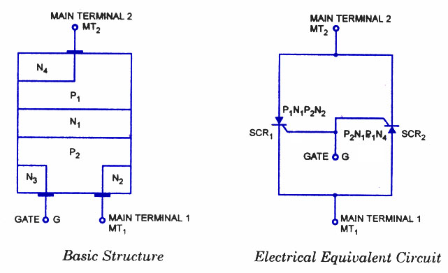
The arrangement of the triac is shown in figure. As seen, it has six doped regions. The gate terminal G makes ohmic contacts with both the N and P materials. This permits trigger pulse of either polarity to start conduction. Electrical equivalent circuit and schematic symbol are shown in figure. b and figure. c respectively. Since the triac is a bilateral device, the term anode and cathode has no meaning, and therefore, terminals are designated as main terminal 1. (MT1), main terminal 2 (MT2) and gate G. To avoid confusion, it has become common practice to specify all voltages and currents using MT1 as the reference.
Though the triac can be turned on without any gate current provided the supply voltage becomes equal to the breakover voltage of the triac but the normal way to turn on the triac is by applying a proper gate current. As in case of SCR, here too, the larger the gate current, the smaller the supply voltage at which the triac is turned on.
Triac can conduct current irrespective of the voltage polarity of terminals MT1 and MT2 with respect to each other and that of gate and terminal MT2. Consequently four different possibilities of operation of triac exists. They are: When terminal MT2 is positive with respect to terminal MT1 current flows through path P1-N1-P2-N2.
The two junctions P1-N1 and P2-N2 are forward biased whereas junction N1 P2 is blocked. The triac is now said to be positively biased. Though the flow path of current remains the same as in mode 1 but now junction P2-N3 is forward biased and current carriers injected into P2 turn on the triac. When terminal MT2 is negative with respect to terminal MT1, the current flow path is P2-N1-P1-N4. The two junctions P2-N1 and P1 - N4 are forward biased whereas junction N1-P1 is blocked. The triac is now said to be negatively biased. Though the flow path of current remains the same as in mode 3 but now junction P2-N2 is forward biased, current carriers are injected and therefore, the triac is turned on.
Generally, trigger mode 4 should be avoided especially in circuits where high di/dt may occur. The sensitivity of triggering modes 2 and 3 is high and in case of marginal trigger ing capability negative gate pulses should be used. Though the triggering mode 1 is more sensitive compared to modes 2 and 3, it requires a positive gate trigger.
However, for bidirectional control and uniform gate trigger modes 2 and 3 are preferred. 🔗 External reference
Related Circuits
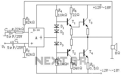
In a power supply circuit with a rating of 15V and a 10W power load, there are notable differences between two circuit configurations. The first configuration (A) uses discrete components in place of an integrated operational amplifier for the...
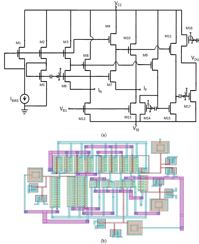
A comprehensive design procedure is proposed for the development of Field-programmable/Reconfigurable Analog Integrated CMOS circuits. Instead of relying on iterative simulation steps to meet design specifications by adjusting the W/L ratios of the FETs, first-order classroom equations are utilized...

This is a single gain-of-100 amplifier with a gain-bandwidth product of 20 MHz. The primary limitation in performance is the low slew rate of 0.3 V/μs imposed by the charging of Ccomp. The effects of slew rate and compensation...

This notch filter is beneficial for tunable band-reject applications in the audio range. The specified values will provide a tuning range of approximately 300 to 1500 Hz. The notch filter is designed to attenuate a specific frequency while allowing others...
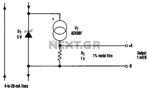
At the core of this circuit is the KTY10 temperature sensor from Siemens. This silicon sensor functions as a temperature-dependent resistor, integrated as one arm of a bridge circuit. A preset potentiometer (P1) is used to balance the bridge...
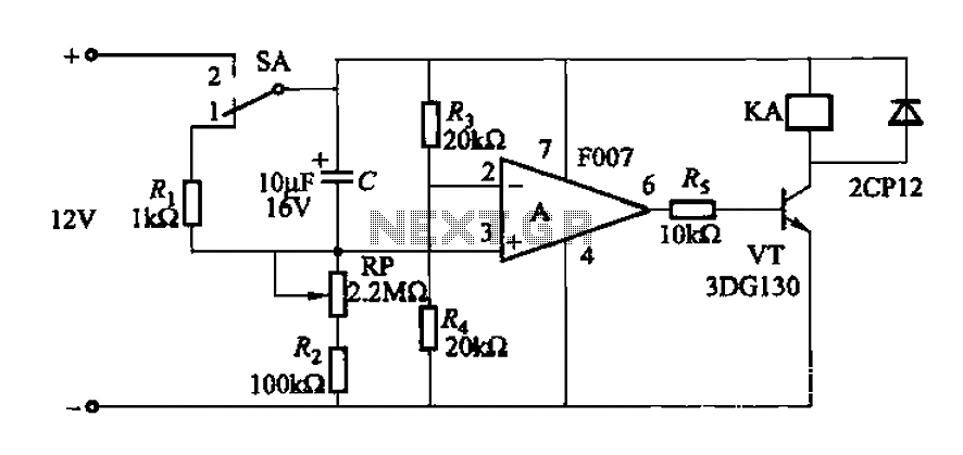
A delay circuit utilizing an operational amplifier functions as a comparator, providing high timing accuracy. The timer's delay range is from 1 to 30 seconds. The delay time is determined by resistors Ri, RP, and capacitor C. By adjusting...
Warning: include(partials/cookie-banner.php): Failed to open stream: Permission denied in /var/www/html/nextgr/view-circuit.php on line 713
Warning: include(): Failed opening 'partials/cookie-banner.php' for inclusion (include_path='.:/usr/share/php') in /var/www/html/nextgr/view-circuit.php on line 713