
Thermometer For 5V Operation Circuit

The KTY10 temperature sensor operates on the principle of varying resistance with temperature changes. As the temperature increases, the resistance of the sensor decreases, which alters the balance of the bridge circuit. This unbalance generates a voltage differential that is read by the moving coil meter (M1). The meter's scale can be calibrated to reflect temperature readings accurately, allowing users to interpret the value directly.
The bridge circuit configuration enhances sensitivity and accuracy, making it suitable for precise temperature measurements. The use of a temperature-compensated Zener diode ensures that the voltage supply remains stable despite variations in ambient temperature, which could otherwise affect the performance of the sensor and the meter readings.
For applications requiring a more portable solution, utilizing a 9-V battery can be advantageous. By substituting the specified components with a voltage regulator, the circuit can maintain efficient power consumption, extending the operational life of the battery while providing reliable temperature readings. This flexibility in power supply options makes the circuit adaptable for various applications, whether in laboratory settings or field measurements.
Overall, this temperature measurement circuit exemplifies a straightforward yet effective design, leveraging the characteristics of the KTY10 sensor and a bridge configuration to deliver accurate temperature readings across a range of conditions. At the heart of this simple circuit is the well-known type KTY10 temperature sensor from Siemens. This silicon sensor is essentially a temperature-dependent resistor that is connected as one arm in a bridge circuit here. Preset PI functions to balance the bridge at 0C. At that temperature, moving coil meter Ml should not deflect, i.e., the needle is in the center position.
Temperature variations cause the bridge to be unbalanced, and hencc produce a proportional indication on the meter. Calibration at, say, 20C is carried out with the aid of P2. The bridge is fed from a stabilized 5.1-V supply, based on a temperature-compensated zener-diode. It is also possible to feed the thermometer from a 9-V battery, provided D1-D3, Rl and Cl are replaced with a Type 78L05 voltage regulator, because This is more economic as regards to current consumption. 🔗 External reference
Related Circuits
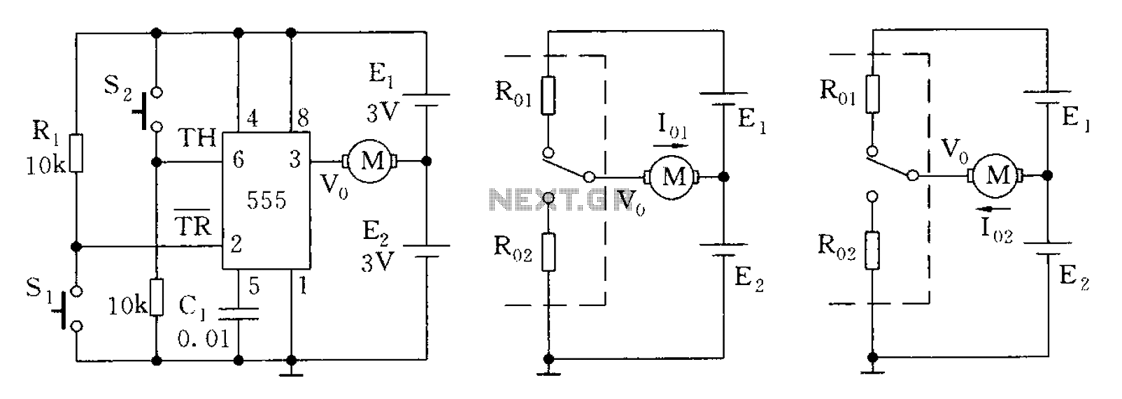
The 555 timer in bistable mode has fewer applications compared to its stable and monostable modes. Bistable mode refers to the circuit configuration based on the R-S (Reset-Set) trigger mode. An example of this is a micro-motor reversing control...
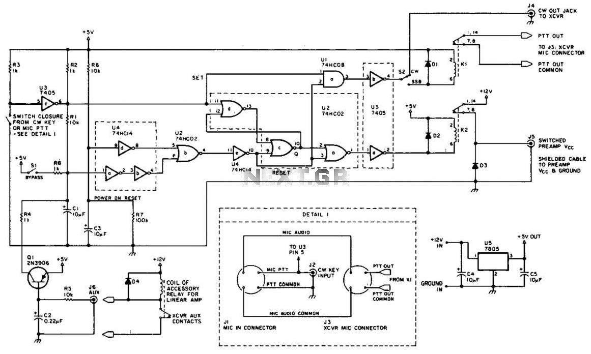
This circuit is beneficial for amateur radio operations in VHF and UHF frequencies, where a mast-mounted antenna preamplifier is employed for reception. The kit manages the transmit-receive (T-R) switching and relay sequencing to prevent high RF levels from being...
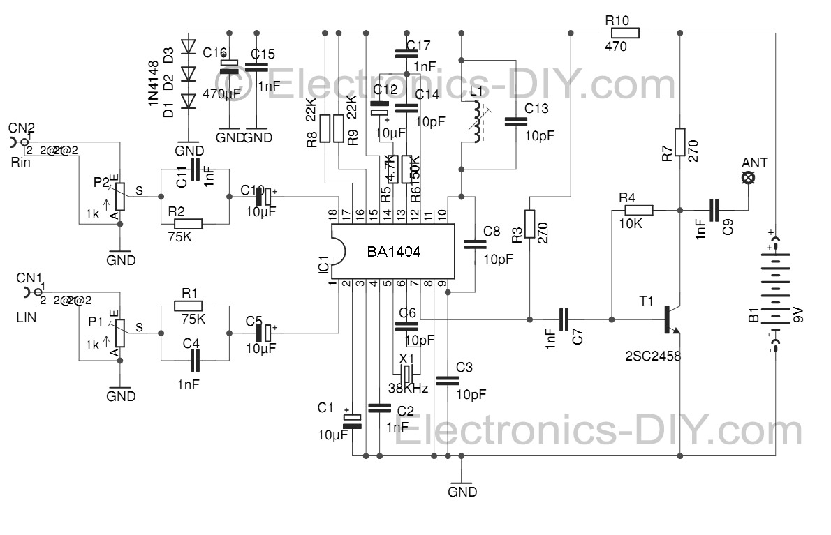
This Stereo FM Transmitter with BA1404 enables the creation of a mini stereo FM station, allowing for wireless audio broadcasting throughout a home. It provides a straightforward method for establishing an audio link without the need for complex wiring....
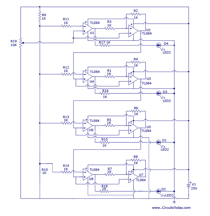
The design originated from the interest in discovering a new technique for analog to digital conversion. The two types of ADC (Analog to Digital Converter) that influenced the development of this circuit are the Flash Type ADC and the...
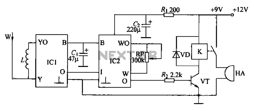
A circuit for an inductive burglar alarm is derived from a radio scanning detection circuit, which includes a signal processing circuit and an alarm circuit. The radar detection circuit module consists of components such as microwave emission, low-pass filtering,...
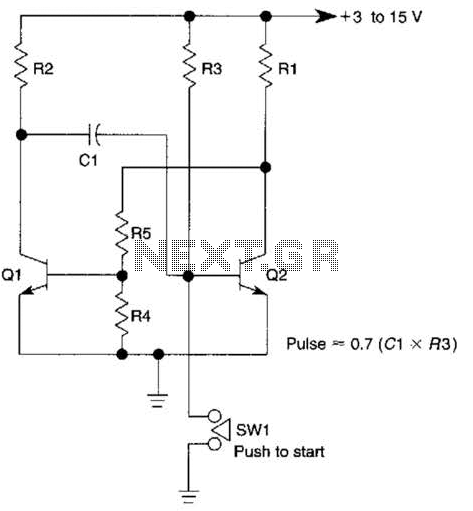
This circuit is activated when switch SW1 is pressed, grounding the base of transistor Q2. The pulse rate is approximately equal to 0.7 multiplied by the product of resistor R3 and capacitor C1. The described circuit features a transistor Q2,...
Warning: include(partials/cookie-banner.php): Failed to open stream: Permission denied in /var/www/html/nextgr/view-circuit.php on line 713
Warning: include(): Failed opening 'partials/cookie-banner.php' for inclusion (include_path='.:/usr/share/php') in /var/www/html/nextgr/view-circuit.php on line 713